In my last post, I showed how I used an old laptop and an RTL-SDR dongle to track weather balloons. While researching it I found that inexpensive LoRa development boards can also receive radiosonde signals. I assumed they would be more complicated and more expensive to set up, but it turned out to be the opposite. The software installed from my browser in a few minutes and was easy to configure.
A whole prebuilt receiver only cost about AU$33 (US$23) and it came with a small LCD display and battery charging circuitry. The included antenna is not really suitable, but I found it easy to build one.
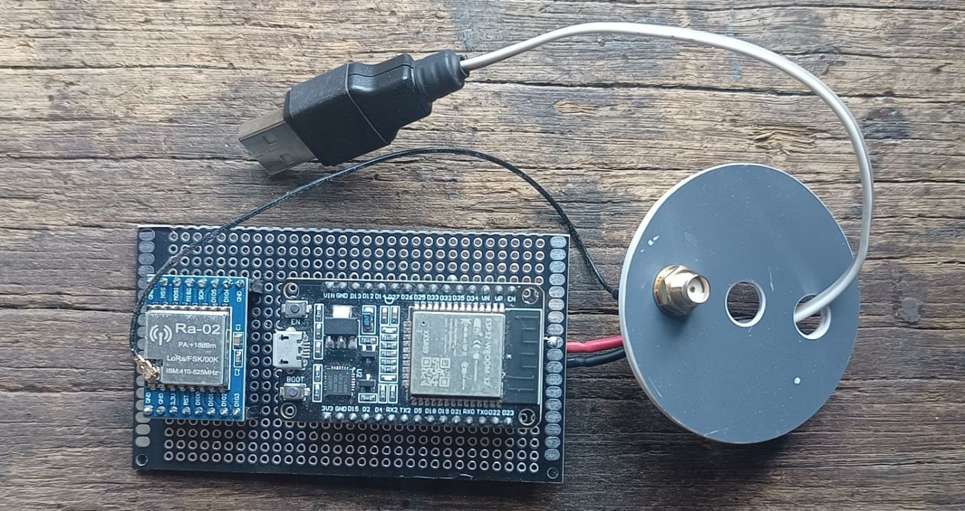
I made a seperate simple receiver from an ESP32 dev module and LoRa module for around AU$13 (US$9) that received signals just as well.
The range with both wasn’t as long as with the RTL-SDR setup, but coupled with a home made antenna it tracked sondes up to 200 km distant.
LoRa modules and radiosonde tracking
LoRa (short for “Long Range”) is a wireless communication technology designed for connecting low power IoT devices over long distances. They are available for different bands and many places have a single band that can be legally used for transmission. In Australia they can be used to transmit on 915-928 MHz. Some countries use the 433 MHz band. It didn’t seem to be an obvious choice for radiosonde tracking but that one is close to the 400MHz frequencies used by many radiosondes. Close enough that the modules can be used for tracking. We are only receiving data so its ok to use these for radiosonde monitoring even though they are not legal for transmission here.
433 MHz LoRa development boards are popular for tracking radiosondes in the field as they are small and inexpensive. These boards include a radio chip (usually an SX127x) that can also receive the FSK signals radiosondes use, as well as an ESP32 and a small (0.96 inch) OLED display.
One thing worth noting is these LoRa boards don’t support all types of sondes, but they do work with Vaisala RS41 sondes which are the most common in the world. There is a table listing compatibility at the GitHub page here.
Another thing worth noting is that cheap LoRa boards, including what I am using here don’t have built in GPS. That’s not an issue when using them as a base station, but it does mean that they don’t automatically update their location on SondeHub when being used mobile. I’ve read that when using the MySondyGO software The device sends decoded data over Bluetooth to the phone app, and the app uses the phone’s GPS for your position, so chasing works without a GPS on the module, but the phone has to stay connected for position reporting to work. I haven’t tested that.
Software
I found a couple of software options, both of which can send data to SondeHub.
The first is rdzTTGOsonde. It shows sonde information on the board’s display and also creates its own WiFi access point, allowing you to connect with a phone or PC to view data and change settings in a browser. It can also join an existing WiFi network, allowing you to reach the same interface from any device on that network and also upload data to SondeHub over the WiFi network.
The second is MySondyGO. It is similar and it also shows data on its display. It differs in that it connects using Bluetooth to a device running their Android or iOS app, which handles the map, tracking, receiver location and SondeHub upload using the phone’s internet connection. I haven’t tried it yet, as I’m currently experimenting with rdzTTGOsonde.
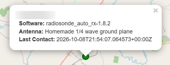
It’s interesting to see what other people are using for their monitoring stations. Clicking a station dot on SondeHub opens info about the station, including the antenna type the user has entered and the software it uses. This user is running radiosonde_auto_rx which is what I am using with my Linux laptop and RTL-SDR.
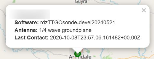
This user is using the rdzTTGOsonde so I expect is running some type of LoRa receiver.
Setup experiments
I decided to experiment with two different LoRa modules.
LilyGo Dedicated LoRa32 module
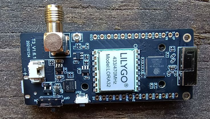
This is a very common module sold by LilyGo (formally TTGO). I purchased one from their official AliExpress store here for AU$32.99. These modules come in different frequency versions. Weather balloons transmit here around 400-405MHz so only a 433MHz module will work. I got the SX1278 433MHz version.
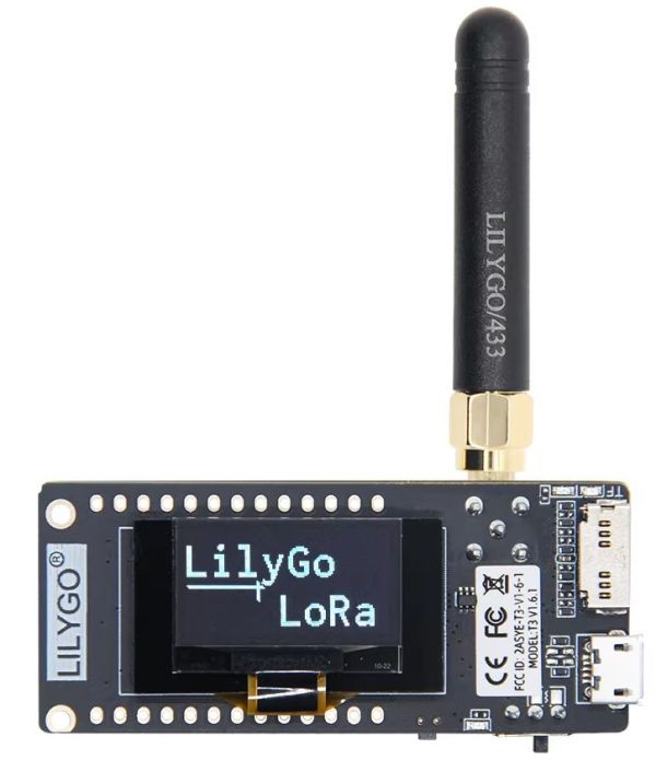
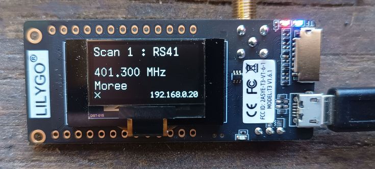
This is the front of the module with rdzTTGOsonde running.
The back of the module.
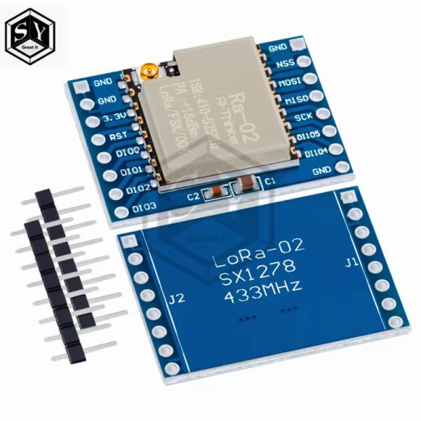
A standard ESP32 dev Module with a separate 433MHZ SX1278 LoRa Module
Standalone LoRa modules are available and I wanted to see if I could use one with an ESP32 module and set it up as a base station running the rdzTTGOsonde software without any modification. I wanted to try placing the electronics up at the antenna and just have a power cable running up to it. This use wouldn’t need a screen or battery charging. I purchased this 433MHZ SX1278 LoRa Module without the antenna for AU$6.91.
Installing rdzTTGOsonde
I started with the LilyGo board and expected installing the software to be difficult. It turned out to be very easy and didn’t require installing anything on my computer.
The rdzTTGOsonde install page offers three options: flashing from your browser (recommended), using the esptool command-line utility, or using Espressif’s Windows Flash Download Tool. I used Option 1, flashing from your browser. It needs a browser with WebSerial support, such as Chrome, Edge, or Opera.
I plugged the board into a USB port and clicked CONNECT. A list of serial ports appeared with only one entry. I selected it. In the next dialog, I chose the latest main release (currently 0.98). Then clicked Install rdzTTGOsonde, and followed the prompts.
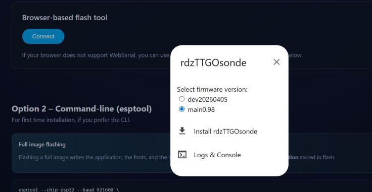
Once flashing finished, I disconnected and reconnected the power, and the board started up.
Accessing
The board has a small OLED display, but it seems to be mainly for status. Configuration is done over WiFi. After flashing I followed the “After flashing” instructions at the bottom of the rdzTTGOsonde install page.
I had disconnected and reconnected the power after flashing so I waited for the board to start its own WiFi access point. It appeared in my computer’s list of networks as RDZsonde. I clicked on it to join using the password RDZsonde.
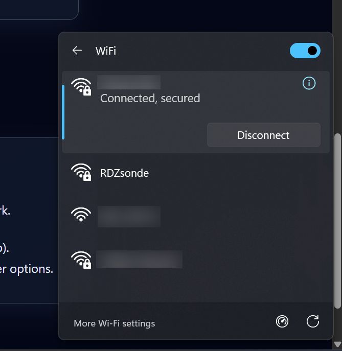
Once connected, the web interface was available at http://192.168.4.1 (or for supported browsers http://rdzsonde.local). Everything can be configured from there, but while connected to the board’s access point my PC had no internet access. I wanted it to connect to our regular WiFi so I could access easily without having to connect to the access port.
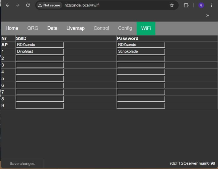
To set up connection to our network I went to the WiFi settings, entered my home network’s name and password, and reset the module.
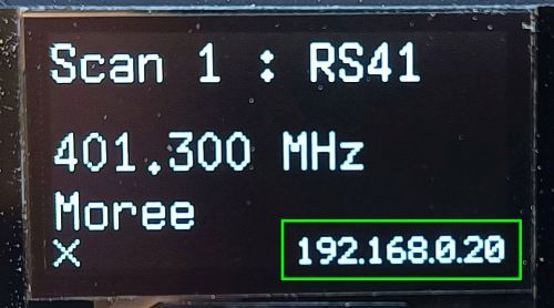
When the board restarted, it showed its new IP for our network on the address on the display. Entering that address in my browser (for example, http://192.168.0.20/) opened the same interface but this time from my regular network, and my PC kept its internet connection.
Configuration settings
It was now time to configure some of the other settings. As I wanted to upload the data to go to SondeHub, I entered my latitude, longitude and altitudeiIn the Config settings.
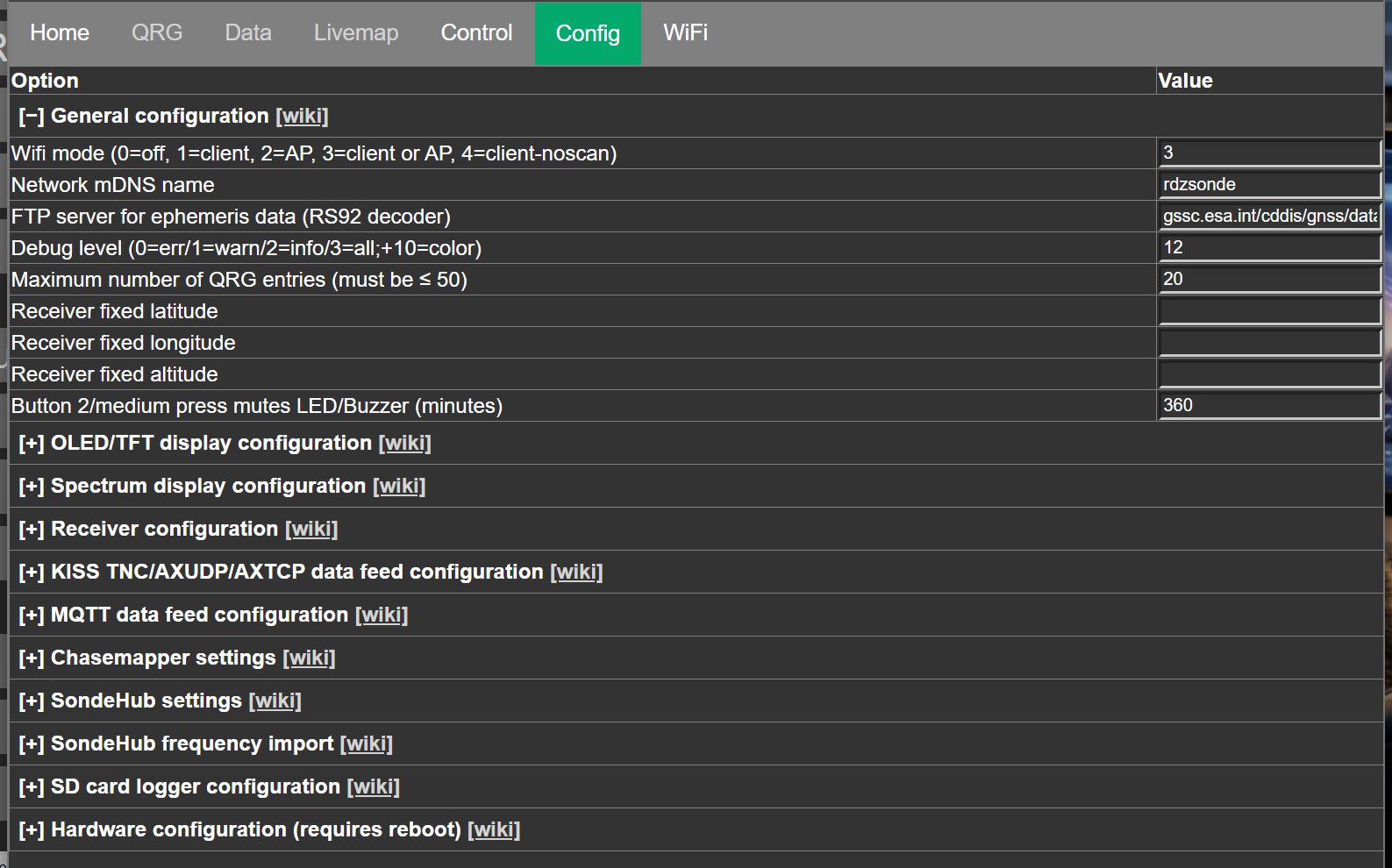
Below in the SondeHub settings I also updated SondeHub location reporting to 1 (‘fixed’ as I am only intending to use this from home at this stage) and entered a Callsign, Antenna and SondeHub email.

There is a helpful wiki with detailed info here.
Reserving an IP address
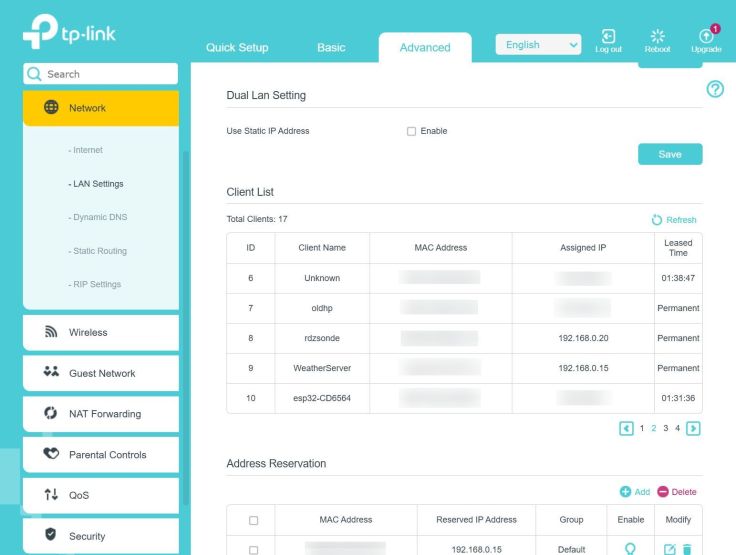
Home routers assign addresses to devices automatically (using DHCP), and a device’s address can change over time. I could have read the address from the board’s display each time, but I wanted a reliable address to bookmark. I was also thinking of mounting the module up high near the antenna to reduce cable losses, where I couldn’t see the display.
On my router I set up DHCP reservation, which tells it to always give the same address to a particular device. Both my current router and my previous one support this. On mine, once the board has connected to WiFi, I go to the network settings and choose Add a device. Then select the device from the list of connected devices, and enter the address I want it to have. Menus vary between routers, so look for terms like “DHCP reservation” or “static lease.” It’s something worth investigating if you are interested in doing this.
Using the Map and setting up scanning
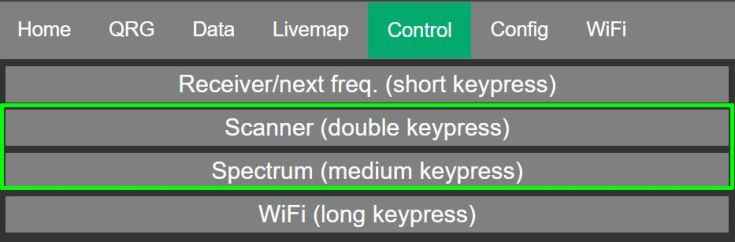
Scanner mode or Spectrum?
Scanning can be based on a defined list or scanning frequencies within a range. This Control can be chosen by clicking on the appropriate button on the Control tab. I haven’t had any success with scanning mode yet.
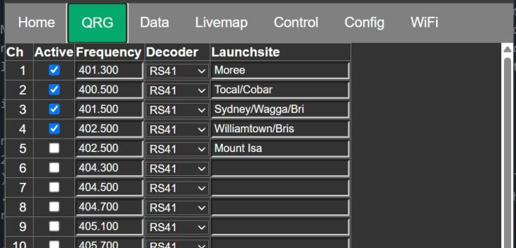
Setting channels
A list of frequencies can be set and enabled from the QRG tab. I got these frequencies from the SondeHub map.
Live Map
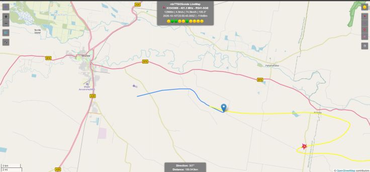
The Livemap tab loads a map with the status of scanning at the top. The default map doesn’t load for me and displays an ‘API key required’ message. Clicking the blue icon on the left loads other maps. I like this one.
Once it locks onto a radiosonde it displays the balloons path. The green and yellow circles indicate received and missed packets of data. They move to the right in a chaser pattern.
Making a receiver with a standalone ESP32 with a separate SX1278 LoRa Module
Now the part I was getting excited about. I wanted to see if I could get the software to work on a regular ESP32 Dev Module with 433MHZ SX1278 LoRa Module. If this worked I planned to use this as a permanent monitoring station. The LilyGo has an LCD, battery management and SD card connector, but these didn’t seem necessary for a base setup.
Connections
I looked at the schematic available for the LilyGo board here and concentrated on the connections between the ESP32 and the SX1278 module. The ESP32 IC is a ESP32-PICO-D4 so not exactly the same as on the Dev module, but for this project AI said it was 100% software and firmware compatible, so I thought there would me a chance the magic smoke would remain contained. Later I found that the pin definitions can easily be set from the Config menu in the software, so other pins could have been used, but using the same as for the LilyGo board is a bit simpler.
These are the connections between the two. As far as I can tell all connections are direct connections except for DIO1 and DIO2 that each have a 22 ohm resistor connected between the two modules. I don’t know why that is, but I included these in my prototype.
| SX1278 LoRa Module | ESP32 Dev Module |
|---|---|
| GND | GND |
| GND | GND |
| 3.3V | 3.3V |
| RST | IO23 |
| DIO0 | IO26 |
| DIO1 | IO33 via 22R resistor |
| DIO2 | IO32 via 22R resistor |
| DIO3 | Not connected |
| GND | GND |
| NSS | IO18 |
| MOSI | IO27 |
| MISO | IO19 |
| SCK | IO5 |
| DIO5 | Not connected |
| DIO4 | Not connected |
| GND | GND |
Next, I collected these parts:
- 433MHZ SX1278 LoRa Ra-02 Module AU$6.50 (US$4.52)
- ESP32 Dev module (for example this one) AU$4.31 (US$3.00)
- IPX to SMA connector for antenna (I used one I already had. If buying one beware that the SMA connectors come in male and female) About AU$1.50 (US$1.00)
- Antenna that I built myself
- Prototype Board (like this). I used a 7 x 9cm board and cut it down to fit into 50mm PVC pipe. About AU$5.79 for 5 (US$4.00)
- Terminal block for power connection
Prototype and software
I connected the two modules together with DuPont style cables and attempted to upload the software following exactly the same steps as I did for the LilyGo module. There was one small challenge. As there was no LCD display I couldn’t see what the IP address it had on my home Network. I logged into my router and could see it there and then followed the steps in Reserving an IP address to set a static address.
Build
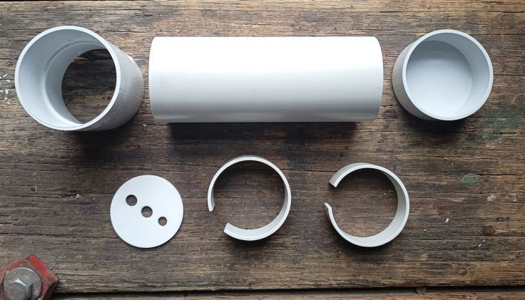
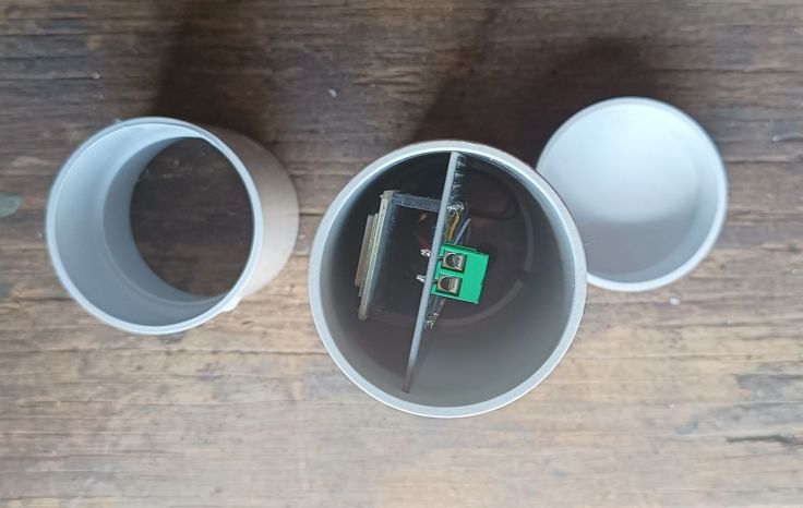
I wanted the module to be housed close to the antenna, so I intended to us 50mm PVC pipe for the housing. To keep the build simple I cut a piece off the side of a 7x9cm protoboard so it was a snug fit in the PVC pipe.
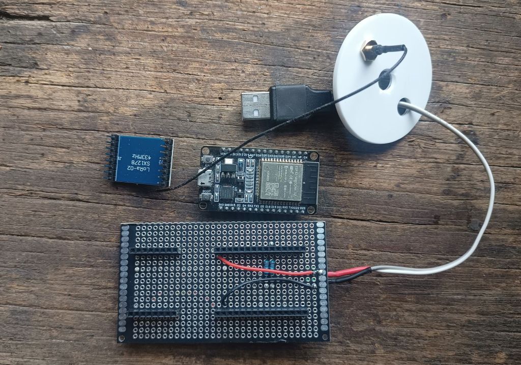
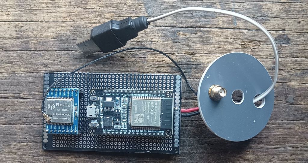
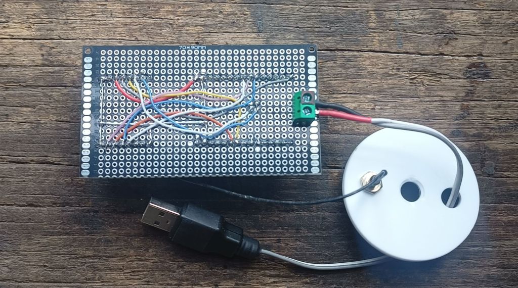
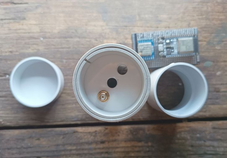
I soldered header pins for both modules to the protoboard. I placed the ESP32 module with the antenna at the opposite end of the board to the other module to keep the ESP32 and its antenna away from the other module. I don’t know if it makes any difference and it does mean I have to remove the ESP32 to reprogram it, but that is easy to do.
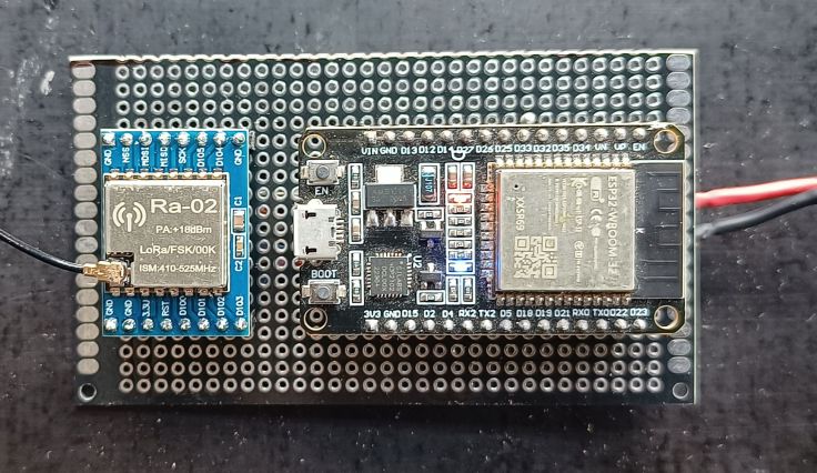
Here are some more images. The wiring is fairly simple. I followed the connections in the table above. The 22R resistors were placed under the ESP32. A terminal block for power was connected to the GND and VIN pins on the ESP32.
Comparison
An interesting question is how does their reception compare. I wanted to test the Homemade SX1278 based setup, the LilyGo board and the SDR-RTL dongle. I only have two identical antennas so I did two tests on two different days.
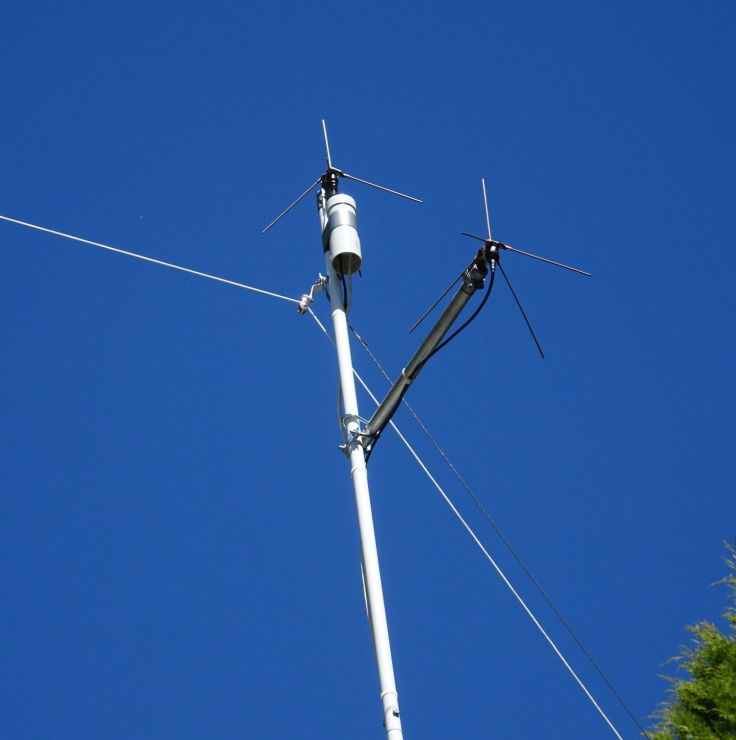
These are the antennas used. They are mounted about 6m above the ground. The top one was used for the home made module and the lower one for the LilyGo board and the SDR.
Homemade SX1278 receiver vs LilyGo board
The first test is to see if the homemade version works as well as the LilyGo board. Both use SX1278 receivers so I expected similar results. It’s worth noting that the home made one was connected to the antenna with only 50cm of coax whereas the LilyGo had a long 5M cable. I tried shorter cables but for some reason these didn’t do as well with the LilyGo board, but they were a different type of coax.
The test monitored a balloon starting around 200 km away and ending around 128 km away. The sky was clear.
Altitude when first received
- Home Made SX1278: 7740 m
- LilyGo: 7895 m
Altitude when last received
- Home Made SX1278: 7376 m
- LilyGo: 8072 m
Packet count
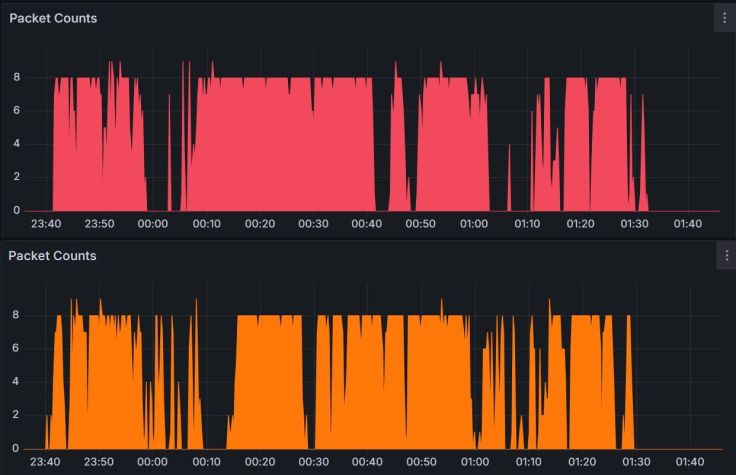
These graphs show the packet count over time. The top (red) is the homemade board and the bottom (orange) is the LilyGo board. The home made received 2484 packets and the LilyGo 2349.
Signal strength
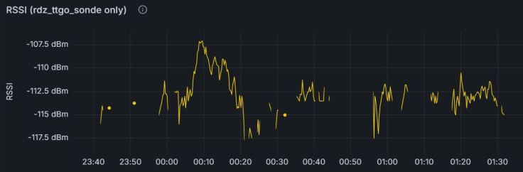
These graphs show the reported signal strength. The blue is the home made board and the yellow is the LilyGo board. Ignore the green, that is someone else.
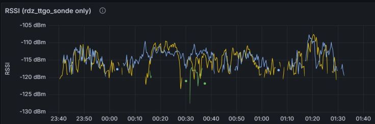
The results were fairly similar. The home made board was slightly better in the test, but it had a much shorter cable to the antenna, so that may account for the difference.
RTL-SDR vs Homemade SX1278 receiver
In this test the balloon travelled in an area between 174 – 200 km from my receiver. The weather was often overcast and there were some showers. The last packet was received by the SDR when the sonde had dropped to 4933 metres and was at an elevation of only 0.59°.
Altitude when first recieved
- SDR: 7724 m
- SX1278: 8414 m
Altitude when last received
- SDR: 4933 m
- SX1278: 5968 m
Packet count
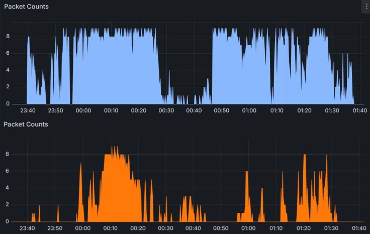
These are two graphs provided by Sondehub and show the packet count over time. The top one (blue) is the SDR. The bottom one (orange) is the homemade receiver. The SDR performed best.
Signal strength
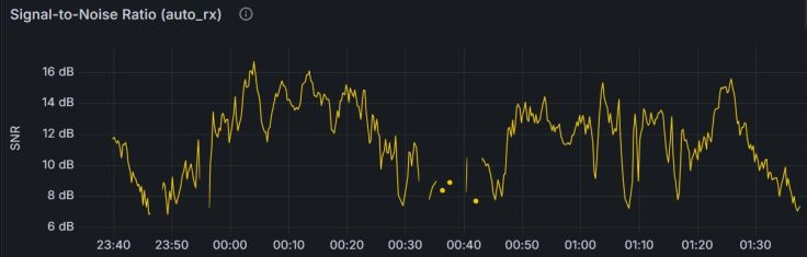
These graphs show the reported signal strength. The two receivers report data differently. The RTL-SDR graph (top) shows signal-to-noise ratio (SNR) in dB, which compares the signal to the background noise. The LoRa board’s graph shows RSSI (received signal strength) in dBm, which is the actual signal power. Because they use different scales, the values can’t be compared directly.
Comparisons
Here is a table based on my results. The costs and build/setup doesn’t cover costs for a housing, cables and an antenna. I mostly used what I had laying around for these.
| Feature | LilyGo Module | ESP32 + SX1278 | RTLSDR + PC |
|---|---|---|---|
| Cost | Module AU$33 (US$23) | Parts AU$13 (US$9) | Dongle AU$57 (US$41) |
| Build / setup | Easiest. Install software, update config settings and connect appropriate antenna. | Medium. Wire up modules, install software, update config settings and connect appropriate antenna. | Reasonably simple for people confident with Linux. More challenging for those without experience. |
| Sensitivity/range | OK | OK | Best |
| Use for | The simplest setup. | Cheap base station. Could be used for mobile, but has no display. | Best for base station. SDR dongle can be used for receiving many other things. |
Wrap up
I really enjoyed this project. I’m now using the home made setup as my main receiving station and it is being powered by the same 5V Mean Well power supply that I am using for some weather modules.
I’ve kept the LilyGo board for taking on holidays. I was able to track a couple of balloons released from Tocal while on holiday in Sydney.
The SDR setup will only be used for special occasions and the RTL-SDR used for other radio experiments.
Two final things I would like to do is to recover a radiosonde and watch a balloon launch, but that may be quite a while away.


Leave a Reply