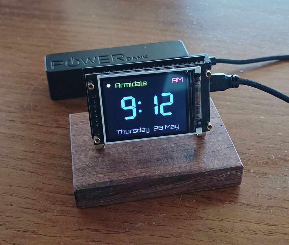
Update 18 Sept 2026: Since making this post the code has been updated to allow the network and time zone settings to be updated over WiFi, rather than hard coding them in the Arduino sketch. This post has been updated to reflect those changes.
If there was only one type of electronics project I was allowed to work on, I think it would be clocks or maybe lights, but this project is about a clock, so I’ll say clocks. I’ve made a few and I regularly get the urge to make more. I’ve been thinking about making one using an ESP32 and LCD display that synchronises with internet time servers.
That’s how this project began. I decided to make it so the electronics are visible and give it to my wife for her desk. The LCD display I used is quite bright so I don’t think this would make a good clock for use at night, but it could be done with a different LCD with a backlight connection for that. This project is intended to sit on a desk and only be powered when the computer is in use.
Let me say before you continue reading that I used Claude AI to generate much of the code. I mainly did the LCD layout and physically assembled the electronics. I know some people are very opposed to using AI for programming. If this is you, then look away now.
Features
The features I wanted are:
- Show time on a cheap 240 x 320 ST7789 LCD display.
- Use a regular ESP32 Dev Module.
- Show time as 12-hour (with AM/PM).
- Show day and date at the bottom of the display.
- Include a toggle switch to toggle between DST (Daylight Saving Time) and standard time.
- ESP32 connects to the internet at startup to obtain the current time, then performs regular updates.
- Add connection information to the display when it is connecting to the internet.
- If the internet connection is lost, the clock immediately makes two additional reconnection attempts, then retries hourly. Connection status is shown on time screen as a coloured dot.
- Use sprites to prevent flickering of display when updating.
- Use the LovyanGFX library for the display.
- Only update the display when the content of the display needs to change.
- Settings reset button to allow settings to be updated using a WiFi access port.
- Brightness control using the same button settings button.
When it is turned on the clock indicates connection information and this updates as connections are established. Here’s what the connection screen looks like during startup.
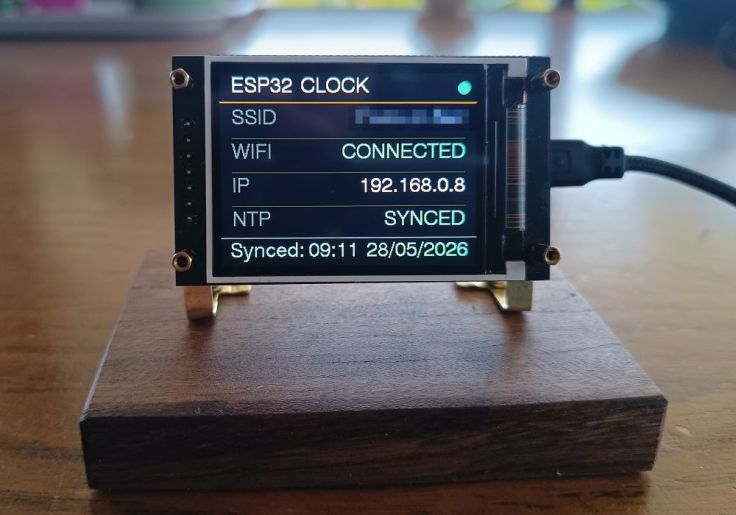
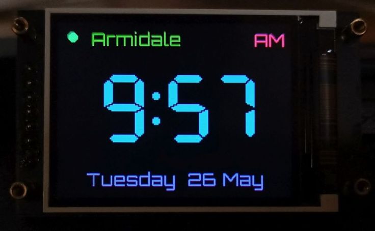
Once connected the time screen displays. Syncing with a time server normally occurs once per hour. The green dot at the top left indicates it has successfully synced with a time server in the last two hours, if it hasn’t it displays red.
This is the clock screen. If using a colour LCD it seems appropriate to use a lot of colour 🙂 The image is quite dark, but that was the only way the camera would give a reasonable representation of the actual colours.
Hardware
LCD
I wanted to keep this simple and use parts I already have. That’s why I chose the 2″ST7789 display.
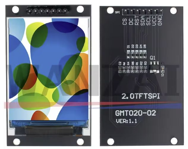
I paid AU$4.17 from AliExpress. The price has increased from this seller, but shopping around will probably find these cheaper. I like these displays, but they do have one downside. They don’t have a pin to set the backlight brightness. One way around this is to use darker colours. I’ve also tested another LCD panels with a connection for a backlight and that also worked. The code is designed for 240 x 320 panels.
ESP32
I used a common garden variety ESP32 Dev Module. This may have been a good time to experiment with one of those super mini boards, but I didn’t.
Slide switch (for DST)
I used a small slide switch with .254″ spaced pins as these are easily mounted on protoboards. I only expect to use it twice a year, so I think it will be good for this.
Push button (for brightness and settings config)
A simple push button switch is used to activate the clocks access point to set network settings and to change the display brighness.
Other bits
I cut down a piece of protoboard to mount the ESP32 and switch. I used 2mm standoffs to hold everything together. Some Female pin headers for mounting the LCD and ESP32. Finally some brass strips and hardwood for the mount.
Schematic
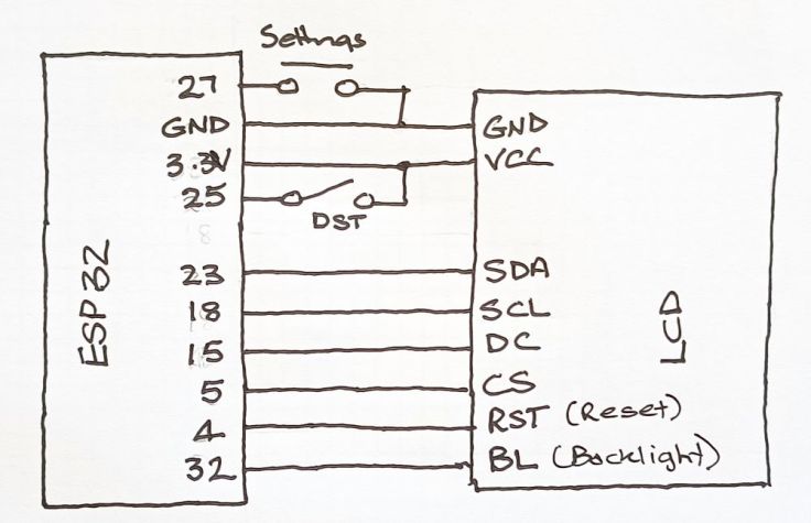
This is the schematic, as you can see it it quite simple with only four parts.
The code
As mentioned previously Claude AI generated most of the code. I’ve included the code on GitHub here, so you can read the readme file there for more info about the code or download it. Feel free to use it and change it.
Colours
Colours can be set for parts of the clock screen; title text (top left corner), AM/PM indicator, time and date. These are set in these lines. Some colours have been defined in the code, or you can use hex values. There is a page of examples here.
// Colors
#define TITLE_COLOR 0x3666
#define AMPM_COLOR  0xF8B2
#define TIME_COLOR  0x05FF
#define DATE_COLOR  0x9999
Network credentials, time zone and title text
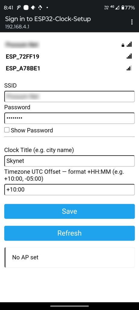
In the initial version these were hardcoded in the sketch, however, I didn’t want to have to reprogram it if I changed the network credentials. I also wanted to make a clock that I could give as a gift and the recipient could easily update these themselves. This was done using the amazing WiFiManager library by tzapu. The clock saves it to flash and reconnects automatically on every reboot after that.
Building it
I was looking forward to a simple build. It probably was three hours of work to complete. I’m slow and had to do a lot of thinking.
I started by cutting a piece of protoboard to be about the size of the display. Then holes were drilled in it that aligned with the holes in the display. I had a cunning plan to add female pin headers onto the protoboard for the display. but alas these didn’t align with the protoboard holes. I had to use wires to make the connections.
The DST switch was mounted on the protoboard and all the connections soldered up. I used 2mm brass standoffs to hold the display and protoboard together.
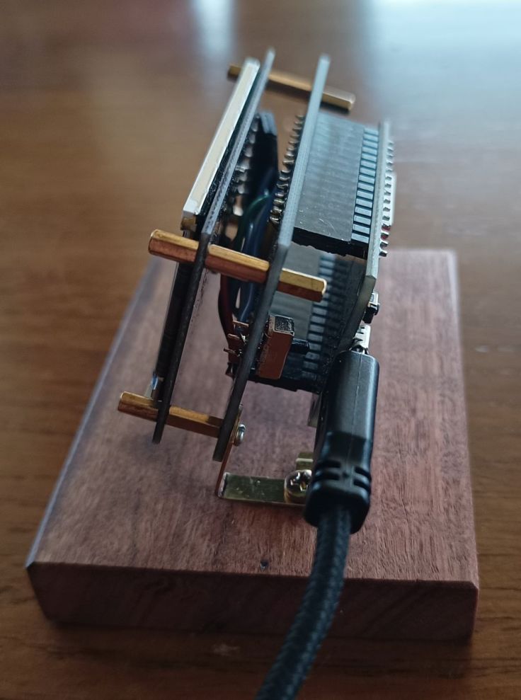
At this point I found I could stop there as it sat at a reasonable angle on the desk. However, it was so light that the stiffness of the USB/power cable made it difficult to position properly.
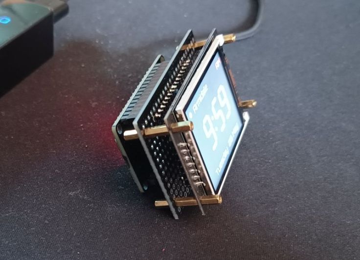
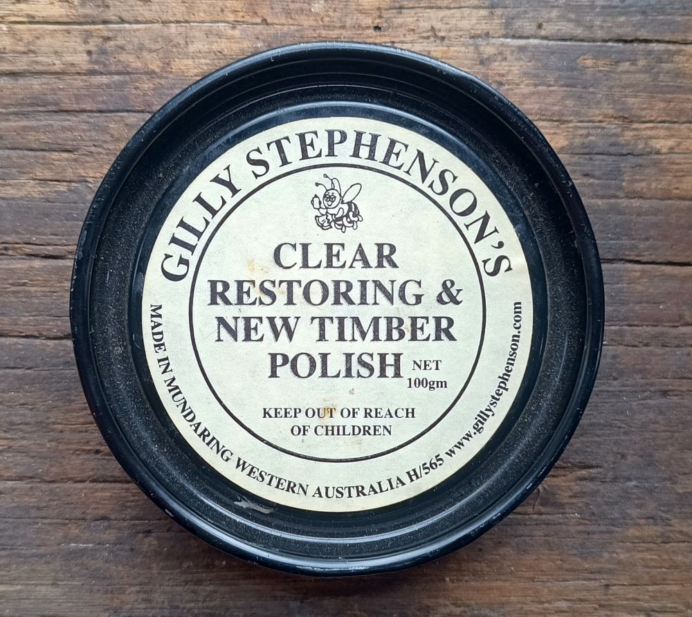
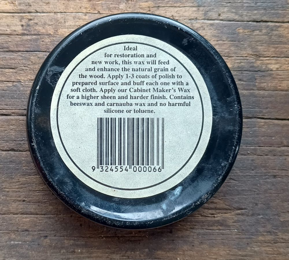
I cut a piece of recycled Australian hardwood. I haven’t had much success with polyurethane recently, but did have some with an old tin of Gilly’s furniture wax I’ve had for years. It’s made in Western Australia and it’s good to use a local product. There doesn’t seem to be any tins like the one I have, but this is their website and I presume one of these is similar. The wax contains beeswax and carnauba wax. The wax is easy to apply and looks good. I’m going to use this more often.
This is the tin I have.
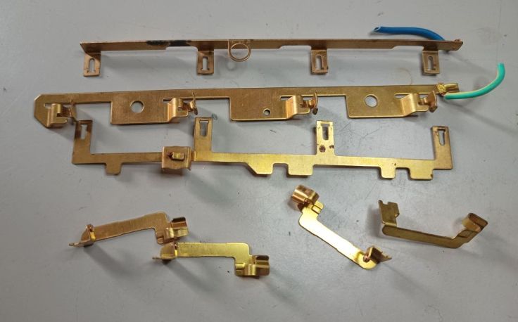
I spent a lot of time thinking of what I could use to mount the clock to the baseboard. Going through a tin of old bits of metal, I found some brass strips I had removed from an old 240V power board, the type that holds four mains power plugs.
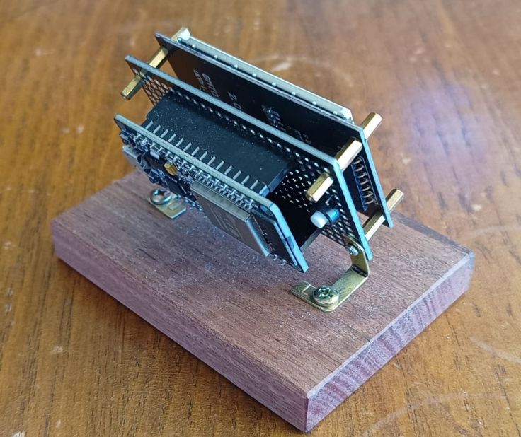
I had to remove some bits, drill holes and bend them, but they came up looking fairly good, considering I didn’t get them aligned very well. Note the small push button with the white button for enabling the access point and brightness control.
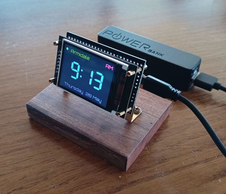
Here is a final shot of it completed.
Operation
Connecting to a network and setting time zone and title text
When the clock is first started after the code has been uploaded, or the settings button is held down at boot, the clock starts a WiFi access point. Using a PC, phone or tablet, look for a network called “ESP32-Clock-Setup”.
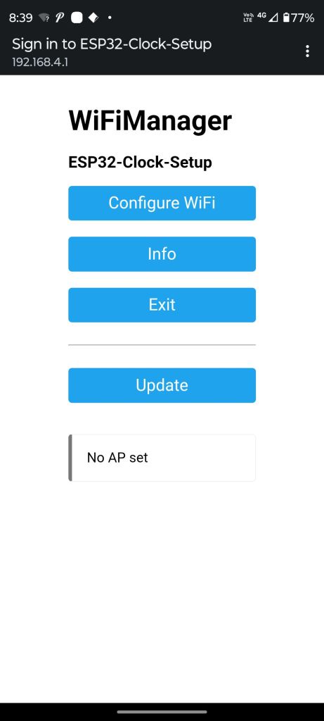
A setup page should open automatically, then select your WiFi network and enter the password. The time offset (time zone) and title text can also be set or updated.
Brightness
When the settings button is pressed during normal clock operation, it steps the backlight down 10% per press and wraps from 10% back to 100%; the level is saved to flash and restored on power-up. This will only work if the LCD as a BL (backlight) connection. The LCD module I used for this project does not.
Daylight savings time
The toggle switch adds one hour to the time and is used to to manually change the clock for DST.
Finally
I’m quite happy with how this turned out. Reusing brass from an old power board is something I’ll probably do again. The furniture wax was also a success. If you are interested, check out the GitHub page for the project as it has more info about it as well as the code.
The clock does what I wanted, it was inexpensive to build and it gave me an excuse to reuse a few bits and pieces that had been sitting around.
The salvaged brass and timber base ended up giving it a bit more character than if I had simply put it in a plastic enclosure and the furniture wax was a success. I’ll probably experiment with more builds like this in the future.
This has earned a permanent place on my wife’s desk.


Leave a Reply