
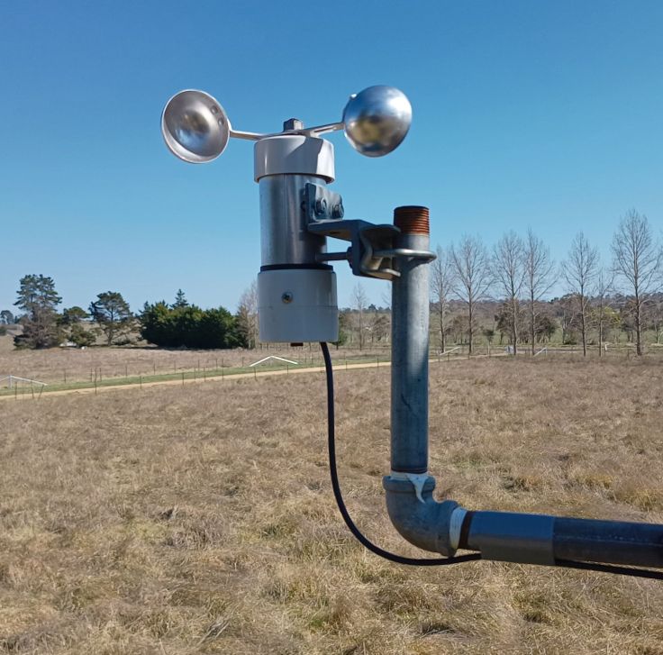
In a previous post I looked at an anemometer that I bought from AliExpress that was built around a cheap toy motor. I wasn’t happy with it so decided to salvage the cups from it for use in a scratch built one using a bicycle hub. It’s been an interesting project and had more challenges than I expected.
Building the anemometer
I’ve been saving a couple of old bicycle wheels for about 20 years with the intention of using them for wind art. I thought they had aluminium hubs, but looking closer they were just cheap steel hubs. It was fairly obvious as they now had lots of surface rust.
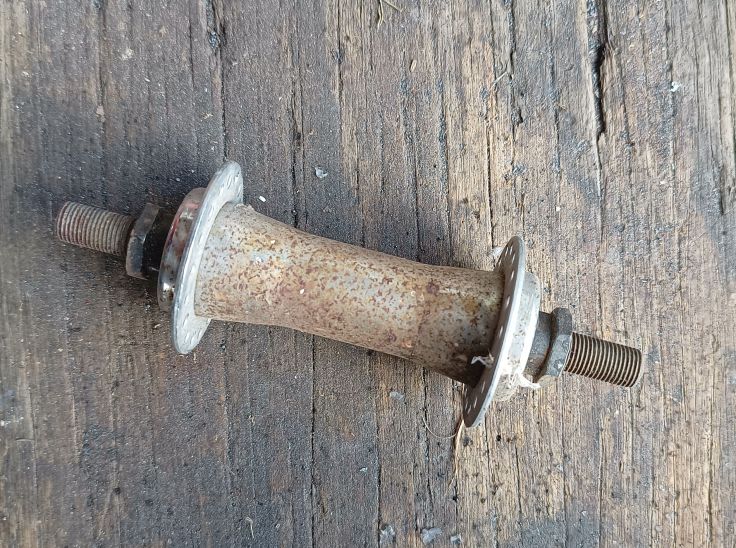
I pulled the first one apart and started cleaning it up only to find that the bearing cone was quite worn. Before disassembling it, it was very hard to turn. I expect it had been too tight when it was being used which would have quickly ground a groove.
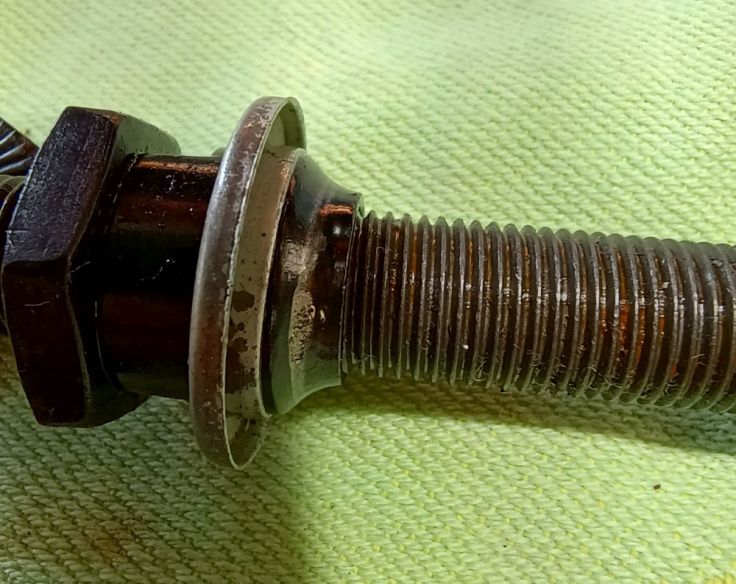
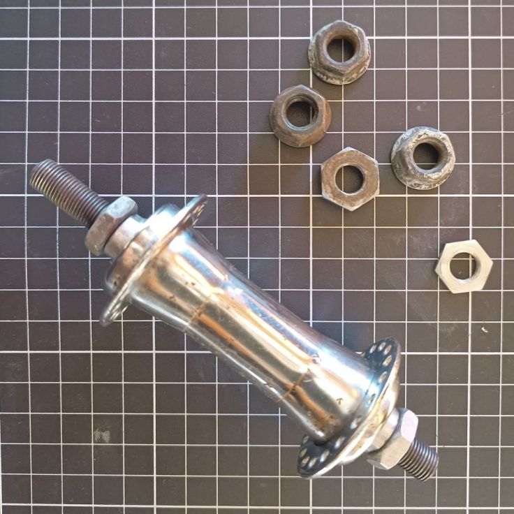
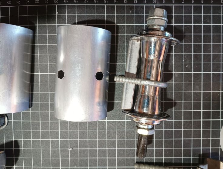
I managed to make one good hub out of the two. I gave it a clean with fine steel wool and it came out looking much better. Comparing it to the picture above it’s impressive to see how much better it looks. I expect it will rust in time, but steel is slow to rust in our climate so it should last for a reasonable amount of time.
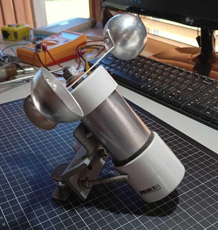
These are the parts I started with. There are three 50mm PVC pipe end caps and a short piece of PVC pipe. The brackets are made from two pieces of steel welded together, but bolting them together would probably have worked just as well. The large U-bolt came from an old TV antenna. Not all the washers were used.
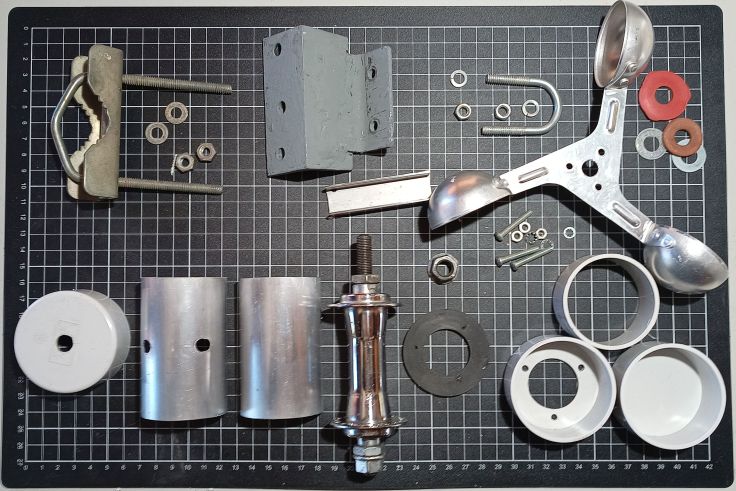
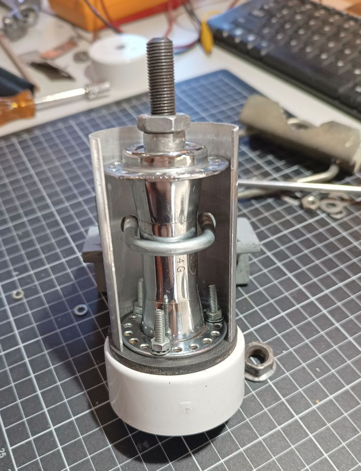
When I made the wind vane I built it using a bicycle hub too and placed some aluminium shroud around it. I have more of that aluminium so decided to build it in the same style. When it does start to rust at least it will not be visible.
I cut down a piece of U shaped steel to fit on the side of the hub to act as a spacer.
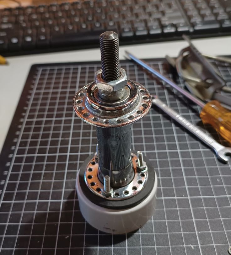
One of the PVC end caps had a hole cut in it and placed on the end of the hub. Three of the spoke holes were drilled out larger and holes drilled in the PVC to allow the PVC to be bolted to the hub. I had a rubber washer that I fitted between them to reduce the amount of water that entered into the electronics. I probably could have riveted it in place, but with the bolts I thought there would be less chance of cracking the PVC.
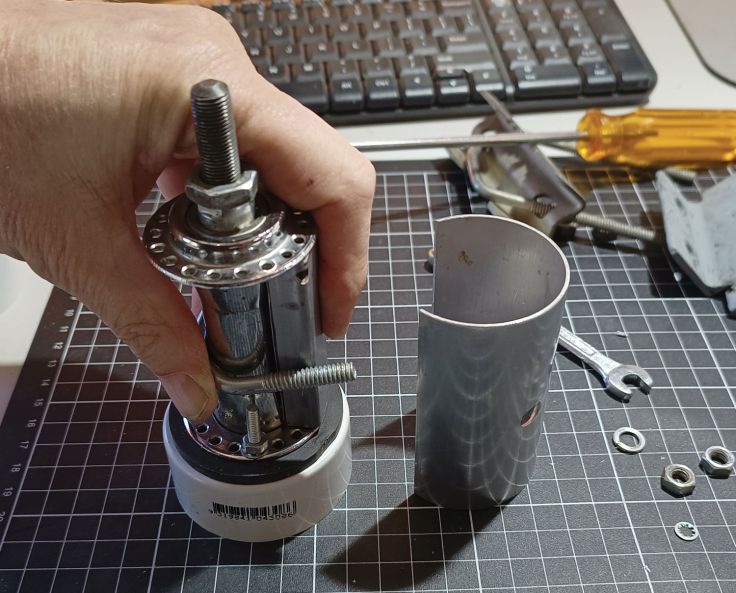
Here’s the glamorous shot of me bolting things together.
Looking ok for a rusty old bike hub.
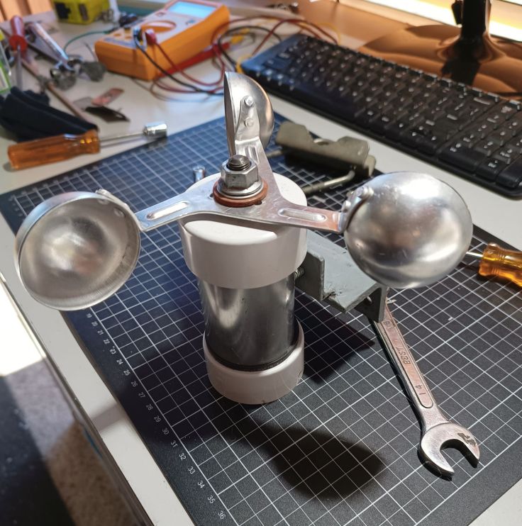
Another PVC end cap went on the top. A hole was drilled in the centre of the cups and a nut held them to the shaft.
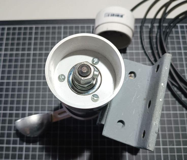
A view of the bottom. A magnet sits on the side of the nut which acts as a trigger for the hall effect sensor.
Here it is mostly finished. Just have to install the sensor in the bottom.
Electronics
The electronics started fairly simply. I had the ESP32 set up to do an analogue read of the output voltage from the old sensor. I am now using a hall effect sensor so set the ESP32 to a digital input.
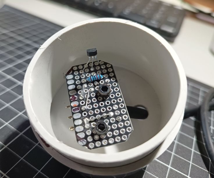
This is the hall effect sensor and pullup resistor. I mounted it on a piece of protoboard to make it easier to mount and adjust.
Calibration
The biggest challenge with building it was calibration. I’ve taken some measurements against known speeds, and its initial comparison with a cheap eBay handheld anemometer was close. Even so, I still don’t have a lot of confidence with its calibration. We are in a windy place and the readings I get are lower than official weather readings. It may be it is because their sensor is higher and more exposed to the wind.
Power issues
The wind sensor sender unit consists of an ESP32, a solar battery, a 18650 Li ion cell and a charger circuit based on a TP4056 charger module and power path. I won’t provide a schematic or go into detail in this post because it is already very long and I am not satisfied with the circuit. I’ll consider a post on that later if I get it sorted out.
When I started, I was using an anemometer that output a voltage and I had no problems with enough battery capacity. That was because the module ESP32 spent most of its time in deep sleep. It was easy enough to wake it briefly to take regular readings and send them to the base unit every minute.
Now that I am using an anemometer that is outputting a pulse each rotation, I’m not sure about the best approach to take. A counter that increments while the MCU remained in sleep would be ideal. I believe that is possible with some MCUs, but I don’t believe it is possible with the ESP module I am using. Another option would be to keep the MCU in sleep mode and set it to wake by the pulses and update a counter. I wasn’t sure if during strong wind that some pulses may get missed, so I haven’t tested that option.
Trying the built-in pulse counting module
I consulted ChatGPT and it recommended using the built-in Pulse Counter. Here is the introduction about it from the Espressif page “The PCNT (Pulse Counter) module is designed to count the number of rising and/or falling edges of input signals. The ESP32 contains multiple pulse counter units in the module. 1 Each unit is in effect an independent counter with multiple channels, where each channel can increment/decrement the counter on a rising/falling edge. Furthermore, each channel can be configured separately.“
ChatGPT said it would run with light sleep. This looked promising, but after a lot of time faffing about and not getting the count to increment I finally challenged her and was told, “Ahhh — you’ve just bumped into the fine print of the ESP32 sleep modes. In light sleep, the ESP32 suspends the APB clock that most peripherals (like UART, SPI, I²C, and PCNT) need to function.“
Another recommended option was to use the ULP, so that’s what I looked at next.
Ultra Low Power coprocessor
ChatGPT also told me “On ESP32 (original), the ULP can sample GPIOs slowly. Not great for high-frequency pulses, but it can detect edges at a few kHz with careful coding. On ESP32-S2/S3, the ULP-RISC-V is more capable.“
Other info suggested it could be a solution including this stackoverflow post. This method uses the Ultra Low Power coprocessor. The ULP can run while in sleep and this can be used to monitor an input. The challenge for me with this approach is that the program for the ULP usually needs to be written in Assembly.
In this video by Andreas Spiess #252 ESP32 Ultra Low Power (ULP) core made easy in the Arduino IDE including 100$ challenge talks about using this tool duff2013/ulptool to program it. I’ve not investigated this yet.
Current solution
At the moment I am using the pulse counter but lowering the CPU frequency to 40 MHz while not sending data. This saves significant power but sometimes the single 18650 battery goes flat at night after cloudy days.
Final thoughts
I enjoyed making the sensor and it didn’t take very long to do. I don’t think this is a great solution if you want accuracy. In that case I would be looking at commercial options. The software and calibration was the main challenge for this project.
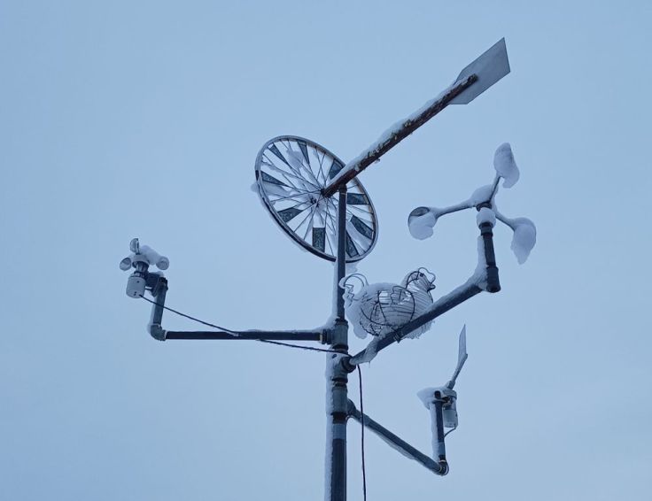
It passed an unexpected snow test.
Here’s a final shot of the setup being inspected by a kookaburra.
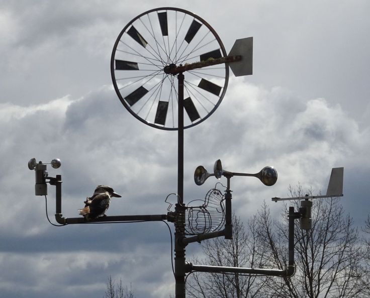
So there you have it. It may not win any precision awards, but at least it survived a snowstorm and passed kookaburra quality control.
Glad to hear your thoughts and if you have made one. I’m particularly interested in ways to run it with low power.

Leave a comment