
This week I learned that 40 years ago I built my first microcontroller project used the first commercially available microcontroller and didn’t realise either of those things until now.
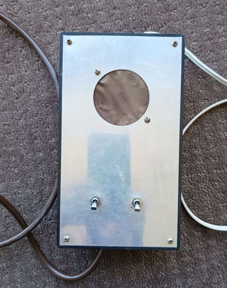
It all began for me around 1981/82 when I built an electronic musical doorbell kit for my sister. It has been in use in two different homes for about 35 years. She gave it back a couple of years ago and told me it no longer worked and it has sat in my shed until last weekend. I got it out and tested and sure enough it no longer worked.
I got interested in the kit while doing work experience in 1981 with an electronics technician. I remember one morning him telling me I would be going out to work on a job with another guy. He wouldn’t say where we were going, he just smiled. After spending a couple of hours trying not to vomit due to the horrific smell at the local sewerage treatment plant we headed back into town. On the way in he demonstrated the blaring horn that they had installed in the car. I’m fairly sure it was based on the kit I have.
I remember at the time I made it I thought it was cool, but it is only now that it feels even a bit more special. In trying to find a schematic I came across the original article and that led off to other info and pretty soon I had my (key)board ready and was off surfing the web.
The reason I find it special is that the project uses a TMS1000 microcontroller. According to Wikipedia and Hackaday this was the first commercially available microcontroller. These were created by Texas Instruments and a lot were made and used, including in TI’s early Speak and Spell and Milton Bradley’s Simon game. But they were not programmed like an Arduino. According to Hackaday “You would not have found this chip for sale in single quantities for experimenters, because its on-board mask ROM could only be programmed at the point of manufacture by TI. Thus all coding was performed in a simulator on a time-sharing mainframe operated by TI. This would generate a deck of punch cards which after a very complex debugging and testing process would be used to generate the masks for ROM coding.“
At first I didn’t even realise what I had was a TMS1000 IC as it is not marked that way. The chip I have is marked as CS107-01 and MP0027A. It was only reading the original instructions where it said “The dedicated version of the TMS1000 is labelled as MP0027 and/or CS10701.“
History of the kit
I’m not sure when it was originally released. I found an advert for it in December 1977 Practical Electronics magazine. A review of the kit was in Practical Electronics, January 1978. Called the chroma-chime, it was designed by Robin Palmer at Chromatronics in Essex, UK. The original kit came with an ABS purpose-built case and was available in kit form or prebuilt. The TMS1000 was also available separately and came with an applications manual. The kit was powered by 2 9v batteries. The tunes were selected by setting a 3 position and 8 position switches. It supported two bell push buttons. The front door button played the chosen tune, while a back door button always played the one tune.

A review of the kit was published in Electronics Australia magazine in April 1978 and the kit was available to purchase from Dick Smith Electronics for AU$49.50. According to the RBA Inflation Calculator that would be around AU$270 now. Quite a lot of money for a doorbell.
I found it interesting that they referred to the IC in different ways. I found “LSI micro-computer circuit”, “dedicated micro-computer chip” and “MOS microprocessor integrated circuit”. As it was early days of microcontrollers perhaps there wasn’t a common way of referring to them.
My version
In September 1979 Electronics Australia published their own plans for a kit and this is what I have. It was a similar circuit with the same IC but it differed in a few ways. It didn’t come with a purpose built case, rather just a large jiffy box. Instead of the two switches to set the front door tune, 4 CMOS ICs were added to perform the automatic sequencing of tune playing. Each button press would advance to the next tune. The circuit was mains powered and ran on 14.3v. That voltage was chosen as it was at the top limit for the CMOS ICs and bottom limit for the CS10701.
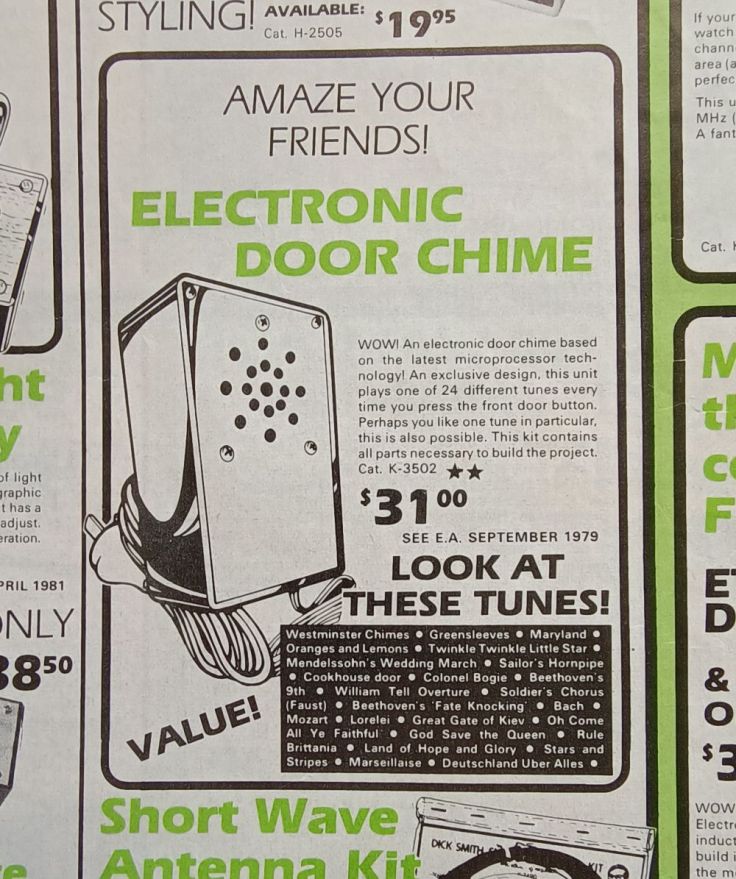
I couldn’t find a price for this kit in 1979, but found it in the 1982 Dick Smith catalogue for $31, which is around the time I built it. That’s around AU$115 in today’s money.
Trying to fix it

As mentioned at the start the one I built no longer worked. While testing it I shorted the connections for the back door which had not been connected and I was surprised that it played a tune. Continuing to push it I noticed it seemed to play 3 different tunes. It should only play one. The front door button still didn’t work at all. Now I haven’t got the kit completely fixed so I can’t tell you the exact part that has failed, but you may be able to work out where the issue is based on the info I’ve given so far. It seemed to me that as the tune is selected by a bank of 3 connections with a bank of 8 connections and that the back door button was playing 3 instead of 1 tune that something had failed in the circuit with the 4 CMOS ICs that manage tune selection.
I was hopeful the CS10701 was still ok and I wanted to confirm that. I don’t have any plans at the moment to use the doorbell, but I was enjoying investigating it. I did the usual board cleaning, resoldering any doubtfull looking joints and even swapped one of the CMOS ICs as I had a replacement for one, but no luck.

The next plan was to try and work out how the tune selection worked. I coudn’t find any data sheet, but I found a circuit diagram of the original kit in the kit instructions in this archive.

Looking at these plans it looks quite simple. A connection is made from one of 3 of the CS10701 pins to another 1 of 8.
This is the circuit diagram of the Dick Smith version. It’s very similar other than those 4 additional ICs and the pinouts on the main IC are drawn a bit differently.
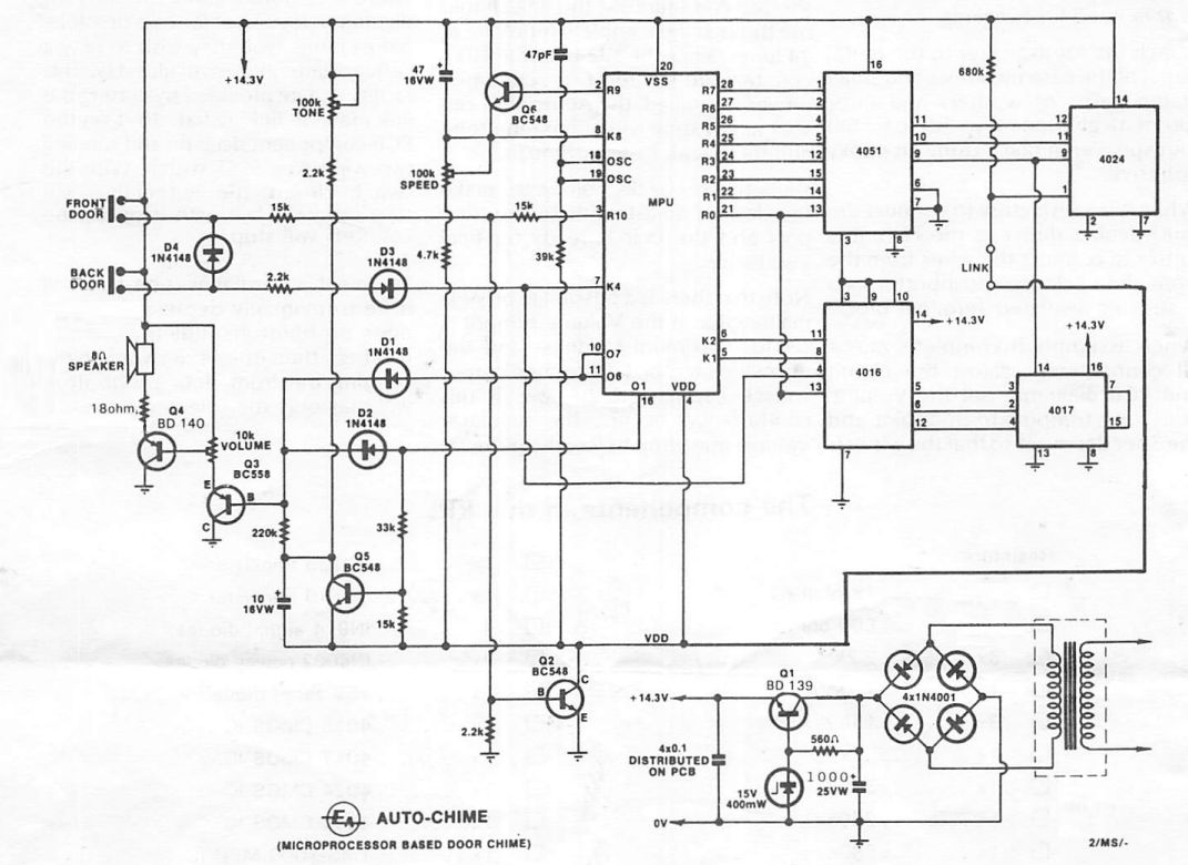
I removed the 4 CMOS ICS and looked at where the pins on the CS10701 came out to the CMOS chips. The board has IC headers so I was able to use a breadboard jumper to do the connections. Bingo. It worked. I’ve made a recording of the tunes, or at least most of them.
The kit is going back to the shed for now, but at least I know it should be able to be easily fixed and I’ve had enjoyment once again from it.

What a coincidence to find your article, just 5 days after you published it.
I also built this ‘Autochime’ from the Electronics Australia article, ‘back in the day’.
It served us well at our previous house for 30 years.
Now we have a solar gate on our ‘new’ property, but don’t want the external ‘gate switch press button’ to open the gate. We like to know when someone is at the gate in case our dogs are out at the time.
So I purchased a separate radio receiver module from the Solar Gate people and use the relay contacts in that module to simulate the ‘door bell’ press button contacts for the Autochime.
I am just in the process of ‘tapping’ the +ve rail of the Autochime to supply the Radio Receiver, so it can sit inside the original case without a second supply.
LikeLike
Hi Peter, that is a coincidence. good to hear of one that is going back into use. I don’t know how many of these were made but it seems like it may have been quite popular. Good luck getting it set up.
LikeLiked by 1 person
I just had one of these in for repair at my shop in NW USA. TR5 had failed, and the unit played continuously when power was applied. I replaced the electrolytic capacitors, as they had drifted out of spec. Very interesting circuit, as well as the cheesy tunes.
LikeLiked by 1 person
Hi Steve, Interesting that someone wanted to get one repaired. They are definitely cheesy tunes.
LikeLike
Hi Garry,
I have just discovered my ancient (1984) copy of the Dick Smith construction paperwork & the modification circuit as well.
Happy to send a pdf if you give me an address.
LikeLike
Hi Garry, good article, I still have my old Dick Smith Chroma-chime kit as my main door bell at home.
Its just started chiming for no reason so I am pulling it down to fix.
If Peter.S. has his instruction I would love them.
LikeLike
Hi. Thanks for the comment. I do have a copy of the Dick Smith plans for the kit now. I’ve sent a copy to your email. BTW, I’ve also edited your comment to hide your email address.
LikeLike
I am also trying to repair a Chroma-chime for my neighbour (it has sentimental reasons for him). It worked recently then died. The one I have has a test button. It did work but now does not. I am concerned that the Microprocessor has died or become damaged. This is the only component that cannot be readily obtained, with the PROM readily ‘burned’.
LikeLike
A very similar project appeared in around 1979 in the UK in a publication called Everyday Electronics. A variation on the Dick Smith/Electronics Australia design but very similar to the original Chromachime in that it used a pair of 9v batteries. The Micro Music Box, as it was called had a three-way switch to select a bank of tunes, and a 4017 decade counter IC to select one of the 8 tunes in sequence. It also used a couple of CMOS gates as High impedance inputs so used a touch pad to trigger it, rather than a conventional push button switch. I built one as an 11 year old and although the box is long gone, I probably still have the MP0027A chip somewhere!
LikeLiked by 1 person
Hi Mike. Thanks for sharing that, that is interesting. I found the construction article on the February 1980 edition of Everyday Electronics on the World Radio History site
LikeLike
I just pulled my EA Autochime down from where it lives. In the cardboard box the kit came in, up in the roof. It had stopped working, but pulling it down and putting it back has it working again. It is amazing it is still going after 44 years. Especially since it is 29C outside today, but 47C in the roof where the Autochime is. It will be 38C outside tomorrow, so the Autochime will be about 56C. And cold every winter (Melbourne, Australia, so never too cold).
I checked the main 100uF capacitor. After 44 years, it is (drumroll…) 115uF, so it went back in.
The construction article is on line here:
https://archive.org/details/EA1979/EA%201979-09%20September/page/n61/mode/2up
LikeLike
Hi Tom. Thanks for taking the time to comment. That is amazing that it is still working, especially as it had stopped and has been in that theat. I live in the northern tablelands of NSW. It’s a bit cooler here. I’ve been to Melbourne a few times, mostly for short visits for work. It was there that I experienced the hottest outdoor temperate. One afternoon I went for a walk at 5:00pm and it was 40 degrees C. I didn’t plan my walk too well and had to walk a couple of blocks in full sun. It was an experience. The next day was only about 24 degrees, far more like what I’m used to. I do like Melbourne though.
LikeLike
Hi there, I purchased a Dick Smith Kit from the early 1980s used it in a couple of houses then it stopped working and it was put asside for a while. Decided to have a look at it again recently discovered it only made a crackling sound when either front or back door switches pushed. I used some contact cleaner on the micro-processor socket, wiggled the processor in the socket – low and behold it worked again. Also decided to spray one of the exposed Pot tracks and the volume increased with a purer sound tone.
Did some googling and found this reference from Electronics Australia https://archive.org/details/EA1979/EA%201979-09%20September/page/n61/mode/2up starting on the numbered page 60. (Page 62 if you use page numbers shown by the browser.)
David
LikeLike
Hi David. Great to hear your kit made a full recovery. It’s satisfying bringing old electronics back to life. It’s amazing how long these things have lasted. I hope it keeps humming along.
Thanks for sharing the Electronics Australia link.
LikeLike