
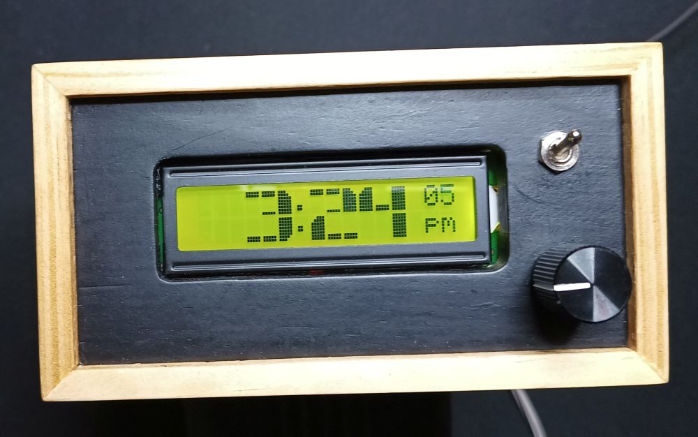
I recently built another clock. This time using a 16×2 LCD display with an I2C backpack. In know these displays are starting to look a bit dated, but I like them. I used a method of display large digits based on Ralph Bacon’s video #23 LCD BIG DIGITS for your Arduino using I2C – Easy! I was pleased with it except the backlight was too bright.
The sketch I am using is based on another clock I did and I had already implemented a menu to set the brightness but that was for a 7 segment LED display which had library support for brightness. The LiquidCrystal_I2C.h library that I use for this display doesn’t seem to support setting the brightness and although I found a mention that some libraries do, I didn’t find one.
A Google search found these methods:
- Remove the jumper from the backpack and connect a resistor across the pins. This sounds like a good solution if the brightness never needs to be changed.
- Leave the jumper off and connect from a PWM pin on the Arduino to the backlight Anode (A) on the LCD display and use PWM to control the brightness Controlling 16×2 LCD backlight (I2C module)
- Leave the jumper off and connect from a PWM pin to the jumper pin on the backpack that goes to anode and use PWM to control the brightness LCD 2004 display, I2C and brightness
I decided to give option 3 a go. Before I connected it up, I thought I would attempt to trace out the circuit and what this change was actually doing.
This is the LCD without an I2C backpack. The backlight LED is on the left. The 100 ohm resistor highlighted and the backlight pins.

This is the backpack with the backlight jumper removed.

I found a schematic here https://www.sunrom.com/p/i2c-lcd-backpack-pcf8574 that looks like the backpack I have. The backlight LED on the display is just connected to the K pin and the A pin via a 100 ohm resistor. Ignoring the rest of the circuit this is the part for the backlight.
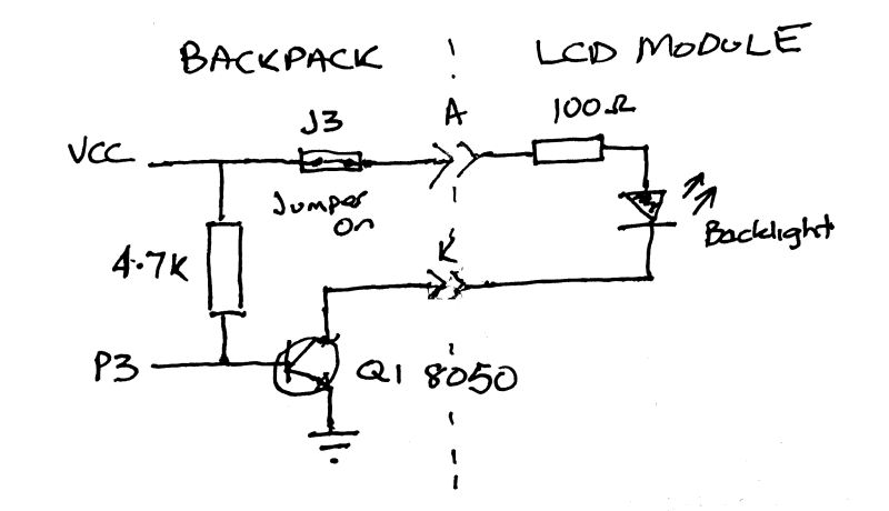
The library supports turning the backlight on and off and I presume this is done via P3 controlling the transistor
By removing the backpack jumper and connecting a PWM pin to the LED jumper pin that goes to the LCD Anode the circuit changes to this
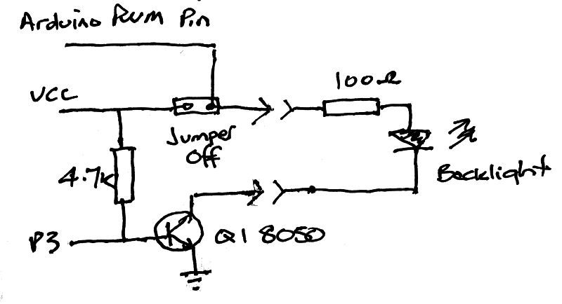
The transistor is still in circuit allowing the library to turn the backlight on and off while the PWM pin controls the brightness.

I’ve got it set up with my clock and so far it is working well and the magic smoke is still securely contained where it should be.

If your host controller is not too busy brightness may be controlled by turning the backlight on and off over i2c. A 32 ms period with 1ms steps works nicely
LikeLike
Hi Richard. Do you have more information on that. I’ve heard that at least one of the I2C LCD libraries support brightness. Is this what you are referring to or is that done separately?
LikeLike