
I’ve been thinking if there is an easy way to make a simple and cheap control knob to replace those cheap quadrature rotary encoders in Arduino projects without the need to change the Arduino code or at least very minimal changes. This would only work if the angle sensor could produce a quadrature output like a standard mechanical encoder, and do it at a useful resolution.
The goal of this project was to see if I could find a magnetic angle sensor that has:
- Quadrature outputs like a mechanical rotary encoder,
- Can easily have the resolution (number of pulses per revolution) permanently programmed into its own built-in EEPROM
- Can then be dropped into a project using ordinary rotary encoder code.
The short answer is, yes there is at least one cheap module, based on the MT6701 IC. The resolution can be programmed in the IC’s built in EEPROM, which can be set and permanently stored using software below. Paired with a hacked potentiometer it makes a great cheap encoder replacement.
This video shows it in action.
But why?
Why not just stick with one of those cheap quadrature rotary encoders? When I used one in a USB Tuning Wheel project as an alternative to a mouse wheel, I discovered how smooth and pleasant this method can be. The knob is silky smooth to turn, and its resolution can be programmed to whatever whatever you want.
These sensors already output data showing the angular position of the magnet, so they can be used with code changes in your sketch. I used this for my Building a Tuning Wheel For PC SDR Radio Using an Angle Sensor project. That worked well, but I thought of a couple of cases where having a quadrature output may be useful.
- It makes it easier to use the sensor in a project that has been coded to use a quadrature output encoder.
- One project I want to try it with is for tuning control of a radio receiver. Using I²C to get the angle data requires polling the sensor. I was concerned that the constant data transfer may add extra noise to the radio, whereas I thought using it with quadrature output could be quieter, particularly when the tuning knob is not being rotated.
Exploring options
It started when I was looking at angle sensors for a wind vane project. I ordered a couple of different sensors from AliExpress including a module with a MT6701 sensor. Both the information page and datasheet say that the resolution is user programmable and that it can be set in EEPROM. Once programmed, it remembers the setting.
It is a magnetic angle/position encoder IC mounted on a breakout board. It works by having the included magnet suspended on a shaft 1 – 3mm above the IC. It can output the position data in several ways. These include SPI and PWM. There is also UVW which outputs three phase-shifted square wave signals used for brushless DC motor commutation and initial rotor positioning.
Finally there is ABZ mode. This provides a quadrature output similar to those cheap rotary encoders. It looked like the resolution could be set from 1- 4096 pulses per revolution (user programmable). While the datasheet mentioned programming it, I couldn’t see information about setting the resolution in EEPROM.
Existing code and libraries
I looked online to see if anyone had posted information about this, but came up empty, but I couldn’t find any. I did find two libraries.
The SimpleFOC Driver and Support Library has drivers and supporting code for a large number of Field-Oriented Control sensors including both the MT6826 and MT6701, but I couldn’t see that it had code to program the EEPROM.
The Noran Raskin’s MT6701 library supports the MT6701 on the ESP32. It supports reading angular positions in radians and degrees, calculating rotational velocity in RPM, and smoothing RPM values with a moving average filter. Sounds like a useful library, but it doesn’t appear to support programming the EEPROM either.
The module
This is the module I purchased. It cost AU$1.98 when I purchased it, but it looks like it is no longer on special. Many sellers stock it, so you may find a better deal. It’s not an affiliate link and I don’t make any money from this blog. Note the module is called MT6701QT and has a lot of the pins broken out. There are other modules with this or other versions of this chip. This is the one I recommend.
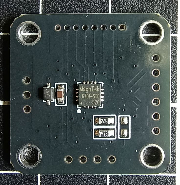
Connections
The IC has 16 pins. 5 of them are not connected according to the datasheet. That leaves 11 pins used. The module has 21 pins so clearly something is going on. I believe they are all used, it is just some on the PCB are connected together. It looks like each side of the PCB has the pins needed for different use cases.

There are three pins marked VDD. This is for the power supply (3.3 – 5V). There are four ground pins, two marked GND and the other two just marked G.
Looking at just the pins on the I²C (left side of the image) and ABZ (top of the image) sides we have.
| I²C side for Programming | ABZ side For Encoder | Function |
|---|---|---|
| VDD | VDD | Power supply 3.3 – 5V |
| Z | Digital Input/output Not used in this project | |
| SCL | B | Encoder Signal A, or I²C data SDA |
| SDA | A | Encoder Signal B, or I²C clock SCL |
| GND | G | Ground |
| M | Selects ABZ (Encoder) or I²C (for programming in my case) mode Connect to ground for ABZ (Encoder mode) Has built-in 200KΩ Pull-up Resistor |
Looking at this table you can see that not only are the power and ground connections shared. SCL and B go to the same pin on the IC and SDA and A go to the same pin. This means you could just use the pins on the ABZ side of the module for both programming or using it as an encoder. It’s the M pin that sets the function of the sensor. It has a built-in pull-up resistor. Leaving it unconnected puts it in I²C mode and connecting it to ground places it in ABZ mode.
The module didn’t come with header pins. I realised why when I tried to connect them. The pin spacing is 2mm not the typical 2.54 mm spacing. I managed to solder 2.5mm pins but I had to bend the legs to make it work. I soldered pins to both edges, but this was partly because I didn’t realise they were shared at the time.
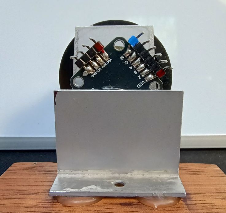
The knob setup
The module does not come with any hardware for a knob. When I was working on the Building a Tuning Wheel For PC SDR Radio Using an Angle Sensor project, I found using bits from a potentiometer were quite a simple and very effective way to set it up. I have written a short article showing how I did this in this post Converting a Potentiometer For Use With a Magnetic Rotary Encoder.
Here is a shot of the setup I used for testing made from a gutted potentiometer.

My new friend Claude helps
I didn’t attempt to write this code myself as this is beyond my programming knowledge. I had tried to see if anyone had done this, but couldn’t find anything. I decided this was another time to try vibe coding. I had not used Claude before, but have heard good reports about it so gave it a try.
The initial prompt I gave Claude was “I have a MT6701QT angle sensor. I want to program in it so that I can change the ABZ Resolution in its EEPROM. I want to connect it to an ESP32 for programming it and use the Arduino IDE. Is this possible. This is the datasheet https://www.novosns.com/enfiles/MT6701_Rev.1.8.pdf“. I must have done this in a rush looking back at the poor grammar. Even so it seemed to understand what I was asking. It came back with:
“I’ll fetch the datasheet to understand the MT6701QT’s programming requirements…. Yes, this is absolutely possible! The MT6701QT has a built-in EEPROM that can be programmed via I²C interface, and the ESP32 is perfect for this task with Arduino IDE.”
I asked Claude to write some code to update the EEPROM so that a chosen resolution can be stored. There was a bit of going back and forth as I realised that I didn’t need to change the resolution of the Z output, only A and B.
I then got it to change from running on an ESP32 to an Arduino Nano. The datasheet says that the power supply for the module is 3.3~5.0V, but for programming the EEPROM the supply needs to be greater than 4.5V. Swapping to a 5V Nano seemed to be the simplest solution.
Next I asked it to add some diagnostics as I couldn’t get it to communicate with the sensor. This highlighted an issue with AI. It doesn’t work well with an incompetent user. I had connected the data pins to D4 and D5 instead of A4 and A5. I changed them over and it burst into life.
This is the final code. It is almost completely written by Claude, It is much longer than is strictly necessary as it still contains all the diagnostic bits.
UPDATE 9 Feb 2026: I’ve updated the code to make it easer to use. It is also available in my Github MT6701_AB_EEPROM_Programmer.
/*
  MT6701QT EEPROM Programmer for Arduino Nano (5V)

  Generated with the assistance of Claude AI

  This program is free software: you can redistribute it and/or modify it under the
  terms of the MIT License https://opensource.org/license/mit

  THE SOFTWARE IS PROVIDED "AS IS", WITHOUT WARRANTY OF ANY KIND

  This sketch programs the AB Resolution in the MT6701's EEPROM
  The Z pulse width is NOT changed - it retains its current value

  Hardware Connections:
  - MT6701 VDD      -> Arduino 5V
  - MT6701 GND      -> Arduino GND
  - MT6701 A        -> Arduino A4 (used for both I2C SDA and encoder A)
  - MT6701 B        -> Arduino A5 (used for both I2C SCL and encoder B)
  - MT6701 Z        -> Leave unconnected

  IMPORTANT: Arduino Nano provides stable 5V which is perfect for EEPROM programming!

  How it works:
  1. Reads current configuration from MT6701 EEPROM
  2. Programs new AB resolution (while preserving Z pulse width and other settings)
  3. Sends programming command sequence per datasheet
  4. Waits 650ms for EEPROM write cycle to complete
  5. Verifies the programming was successful
  6. Requires power cycle to test new setting has been stored

  How to use:
  -----------
  STEP 1: Set your desired resolution below:

    #define DESIRED_AB_PPR 64

  STEP 2: Choose operating mode:

    #define ENABLE_PROGRAMMING false    // false = READ ONLY (safe)
                                        // true  = PROGRAM EEPROM

  STEP 3: Upload and open Serial Monitor (9600 baud)

  STEP 4: After successful programming:
    - Set ENABLE_PROGRAMMING back to false
    - Power cycle the MT6701 (disconnect/reconnect VDD)
    - Set ENABLE_PROGRAMMING false and upload again to verify new settings

  MT6701 Data sheet: https://www.novosns.com/enfiles/MT6701_Rev.1.8.pdf
*/

#include <Wire.h>

// ========== USER CONFIGURATION ==========

// Set your desired AB resolution here (1-1024 PPR)
#define DESIRED_AB_PPR 64

// Operating mode:
//   false = READ ONLY (safe - just displays current settings)
//   true  = PROGRAM EEPROM (CAUTION - writes to EEPROM)
#define ENABLE_PROGRAMMING false

// ========================================

// Compile-time safety check
#if ENABLE_PROGRAMMING
  #warning "WARNING: EEPROM PROGRAMMING IS ENABLED! Set ENABLE_PROGRAMMING to false after programming."
#endif

// MT6701 I2C Address (7-bit)
#define MT6701_ADDR 0x06

// EEPROM Register Addresses
#define REG_ABZ_RES_HIGH  0x30
#define REG_ABZ_RES_LOW   0x31
#define REG_ZERO_MSB      0x32
#define REG_PROG_KEY      0x09
#define REG_PROG_CMD      0x0A

void setup() {
  Serial.begin(9600);
  delay(2000);

  Serial.println(F("========================================"));
  Serial.println(F("  MT6701 EEPROM Programmer"));
  Serial.println(F("  Arduino Nano (5V) Version"));
  Serial.println(F("========================================"));

#if ENABLE_PROGRAMMING
  Serial.println(F("\nMODE: PROGRAM EEPROM"));
  Serial.println(F("*** WARNING: EEPROM PROGRAMMING ENABLED ***"));
  Serial.print(F("Target AB Resolution: "));
  Serial.print(DESIRED_AB_PPR);
  Serial.println(F(" PPR"));
#else
  Serial.println(F("\nMODE: READ ONLY (Safe - No changes)"));
#endif

  Serial.println(F("========================================\n"));

  if (DESIRED_AB_PPR < 1 || DESIRED_AB_PPR > 1024) {
    Serial.println(F("ERROR: DESIRED_AB_PPR must be between 1 and 1024!"));
    while (1);
  }

  Wire.begin();
  Wire.setClock(100000);

  Serial.println(F("Scanning I2C bus..."));
  scanI2C();

  Serial.println(F("\nChecking for MT6701..."));
  if (!checkConnection()) {
    Serial.println(F("\n*** ERROR: MT6701 not detected! ***\n"));
    Serial.println(F("Troubleshooting:"));
    Serial.println(F("  1. VDD -> Arduino 5V"));
    Serial.println(F("  2. GND -> Arduino GND"));
    Serial.println(F("  3. MODE -> Leave unconnected"));
    Serial.println(F("  4. SDA -> Arduino A4"));
    Serial.println(F("  5. SCL -> Arduino A5"));
    while (1);
  }

  Serial.println(F("MT6701 detected successfully!\n"));

  Serial.println(F("=== Current Configuration ==="));
  displayCurrentConfig();

#if ENABLE_PROGRAMMING
  Serial.println(F("\n=== Starting Programming Sequence ==="));

  uint16_t currentRes = readABResolution();
  if (currentRes == DESIRED_AB_PPR) {
    Serial.println(F("Already programmed to desired resolution."));
  } else {
    if (programABResolution(DESIRED_AB_PPR)) {
      Serial.println(F("\nProgramming complete."));
      Serial.println(F("Power cycle required for final verification."));
    } else {
      Serial.println(F("\n*** ERROR: Programming failed! ***"));
    }
  }
#else
  Serial.println(F("\nRead-only mode. No EEPROM changes made."));
#endif

  Serial.println(F("\n========================================\n"));
}

void loop() {
  // Nothing to do
  delay(500);
}

/* ---------- Helper Functions ---------- */

bool checkConnection() {
  Wire.beginTransmission(MT6701_ADDR);
  return (Wire.endTransmission() == 0);
}

void scanI2C() {
  for (byte addr = 1; addr < 127; addr++) {
    Wire.beginTransmission(addr);
    if (Wire.endTransmission() == 0) {
      Serial.print(F("  Device found at 0x"));
      if (addr < 16) Serial.print(F("0"));
      Serial.println(addr, HEX);
    }
  }
}

void displayCurrentConfig() {
  uint8_t reg30 = readRegister(REG_ABZ_RES_HIGH);
  uint8_t reg31 = readRegister(REG_ABZ_RES_LOW);
  uint16_t abRes = readABResolution();
  uint8_t zWidth = readZPulseWidth();

  Serial.print(F("  AB Resolution: "));
  Serial.print(abRes);
  Serial.println(F(" PPR"));

  Serial.print(F("  Z Pulse Width: "));
  switch (zWidth) {
    case 0: Serial.println(F("1 LSB")); break;
    case 1: Serial.println(F("2 LSB")); break;
    case 2: Serial.println(F("4 LSB")); break;
    case 3: Serial.println(F("8 LSB")); break;
    case 4: Serial.println(F("12 LSB")); break;
    case 5: Serial.println(F("16 LSB")); break;
    case 6: Serial.println(F("180°")); break;
    case 7: Serial.println(F("1 LSB (reserved)")); break;
    default: Serial.println(F("Unknown")); break;
  }

  Serial.print(F("  Register 0x30: 0x"));
  Serial.println(reg30, HEX);

  Serial.print(F("  Register 0x31: 0x"));
  Serial.println(reg31, HEX);
}

uint16_t readABResolution() {
  uint8_t highByte = readRegister(REG_ABZ_RES_HIGH);
  uint8_t lowByte  = readRegister(REG_ABZ_RES_LOW);
  return (((highByte & 0x03) << 8) | lowByte) + 1;
}

uint8_t readZPulseWidth() {
  uint8_t reg32 = readRegister(REG_ZERO_MSB);
  return (reg32 >> 4) & 0x07;
}

bool programABResolution(uint16_t ppr) {
  uint16_t regValue = ppr - 1;

  uint8_t reg30 = readRegister(REG_ABZ_RES_HIGH);
  uint8_t newReg30 = (reg30 & 0xFC) | ((regValue >> 8) & 0x03);
  uint8_t newReg31 = regValue & 0xFF;

  if (!writeRegister(REG_ABZ_RES_HIGH, newReg30)) return false;
  if (!writeRegister(REG_ABZ_RES_LOW, newReg31))  return false;
  if (!writeRegister(REG_PROG_KEY, 0xB3))         return false;
  if (!writeRegister(REG_PROG_CMD, 0x05))         return false;

  delay(650);
  return true;
}

uint8_t readRegister(uint8_t regAddr) {
  Wire.beginTransmission(MT6701_ADDR);
  Wire.write(regAddr);
  Wire.endTransmission(false);
  Wire.requestFrom((uint8_t)MT6701_ADDR, (uint8_t)1);
  return Wire.available() ? Wire.read() : 0;
}

bool writeRegister(uint8_t regAddr, uint8_t data) {
  Wire.beginTransmission(MT6701_ADDR);
  Wire.write(regAddr);
  Wire.write(data);
  return (Wire.endTransmission() == 0);
}
Programming
Wiring it up for programming
As mentioned in the module section the AB pins used for the quadrature output are connected to the same pins as the I²C data pins on the module. So make sure the AB pins are not connected to anything when the SDA and SCL pins are connected to the Arduino.
To set it up for programming I have wired it up as follows:
- MT6701 VDD -> Arduino 5V
- MT6701 GND -> Arduino GND
- MT6701 M (Mode) -> Leave unconnected
- MT6701 SDA or A -> Arduino A4 (SDA)
- MT6701 SCL or B -> Arduino A5 (SCL)
Note the Mode pin marked M on the module set the mode of the module. This sets the mode to ABZ or I²C. This has an internal 200K pullup resistor. To use the module with I²C mode, the Mode pin can be connected to VCC or left unconnected. When running it in ABZ mode the Mode pin needs to be connected to ground.
Checking the existing resolution
To check the current EEPROM setting, upload the code to an Arduino Nano with #define ENABLE_PROGRAMMING set to false. This will check the EEPROMs current setting without making any changes.
When I ran the code it reported that the current AB resolution was 1.
Programming the EEPROM
To set the value to something else, set the desired number in the line #define DESIRED_AB_PPR 64. For the radio I later tested with I found 50 was fairly good.
Set #define ENABLE_PROGRAMMING to true so that the EEPROM is updated. Upload the code to the Nano and run it again.
The output in the serial monitor shows if programming is successful.
Checking the programming was successful
Finally, to ensure that the value is not lost when the module is powered down, change #define ENABLE_PROGRAMMING back to false and upload the code and run it again. If it is left as true as it will only write to the EEPROM if the value in the EEPROM is different to that in the sketch, so this is not critical.
Disconnect the Nano to power it down. Then reconnected it back up and check the serial monitor. This is to confirm that the value has been stored and survives a power cycle.
At this point I tried it with some sample encoder code I have and then tried it in a radio circuit I had set up.
Testing it in an existing circuit
I have SI4732 radio set up on a breadboard. It uses the SI4735-Radio-ESP32-Touchscreen-Arduino Gert PE0MGB.
This table shows the change in connections going from the existing encoder to the MT6701. Basically, the only difference is the MT6701 has a connection to 3.3V. This is all I have done in the demo video at the top of this post.
| Existing Encoder | MT6701 | ESP32 |
|---|---|---|
| GND | GND | GND |
| OUT A | A | D16 |
| OUT B | B | D17 |
| VCC | 3.3V |
Potential issues
It occurs to ne there are a few potential issues. The magnetic absolute encoder outputs incremental quadrature signals, which is fundamentally different from a traditional incremental encoder with physical detents. This has at least two differences.
Firstly there is no tactile feedback. For some cases that is ok, but may not be for others.
Secondly, some code written for encoders with detents rely on one output always being high at each detent, creating stable resting states at each detent. I’ve tested with some of the code I use and it didn’t seem to be an issue. I asked Claude about it said, good code doesn’t rely on this—but some simple implementations might. “good code does NOT rely on this, but some simple implementations might have issues. Interrupt-Based Encoders (Most Common – Works Fine) Most Arduino encoder libraries use edge detection and don’t care about resting states. Polling-Based Encoders can have issues.
Finally, cheap rotary encoders often use pullup resistors or use inbuilt pullup resistors for the A and B pins. The MT6701 module doesn’t need these. Claude advised:
“Pull-up resistors on A and B pins are generally fine and won’t damage anything, but they’re unnecessary and could potentially cause issues in some situations.”
“Most likely scenario: Your existing pull-ups will work fine with the MT6701 without any changes. The MT6701’s push-pull outputs are strong enough to override typical pull-up resistors (10kΩ-47kΩ).
For best performance and lowest power consumption: Disable or remove the pull-ups since the MT6701 doesn’t need them.”
“The safest approach: Try it first with existing pull-ups. If you see any issues (jittery readings, poor high-speed performance), then remove them.”
A word of warning
If you don’t already know, I’m just a rando on the internet that enjoys tinkering. I’m not an engineer. In fact I don’t have any qualifications relating to electronics. If you do want to give this a go there are some risks, including;
- I’ve used the code around 10 times and it appears to be working smoothly, however, there may be issues with the code, after all it was written by AI and just like me, AI makes mistakes. It may brick your module.
- Another brand of angle sensor I investigated had a limit allowing the EEPROM to be programmed only 3 times. I couldn’t find any info for this sensor and I have already programmed mine many more times. Keep in mind there may be a limit.
- Even though it worked when I used it with a radio project without code changes, if you use use this as a drop in replacement for a rotary encoder in another project, it may not work without some changes, or worse potentially damage that circuit.
Finally
So what do you think? Brilliant idea or there are better ways? Can you see a use for this or seen it done before? Have you found a reasonably priced dedicated component for this already?

Hi! What parameters in the eeprom need to be changed to switch the module to SSI or PWM mode? My module doesn’t have a CSN pin, so how can I control it via SSI? Thanks!
LikeLike
Hi. On the MT6701 modules I’m using in the post, I’m only using the EEPROM to configure AB (quadrature) behaviour. I’m not using PWM, so I can’t really help with that. I don’t think all MT6701 modules expose all pin. This one https://www.aliexpress.com/item/1005008558918695.html doesn’t expose many pins at all, some expose more, but not all. With the Module I have the pins for SDA and SCL I2C pins become quadrature encoder A pins when the Mode pin is connected to ground. You may be able to program it without the Mode pin but you won’t be able to use quadrature output without being able to set that Mode pin to ground.
LikeLike