I’ve been experimenting with angle sensor modules to use them as a replacement for those cheap rotary encoders. I like those cheap rotary encoders, but I’m looking for something better where the knob turns smoothly and it doesn’t wear out. The cheap encoders wear fairly quickly and then contact bounce can become a problem. Also, detents are not always desirable. Sometimes a smooth rotation is better. Finally, the resolution (detents per rotation) cannot be changed. The ones I have, have 20 detents. Sometimes I want many more.
I’ve tried it out on a couple of projects. The first was Building a Tuning Wheel For PC SDR Radio Using an Angle Sensor and the other was while experimenting with a MT6701QT angle sensor in Replacing a Rotary Encoder with a Magnetic Sensor and Potentiometer.
Those pages don’t have much information about the rotary mechanism.
Behold the potentiometer
After trying a few options I finally found a fairly simple and cheap way to add a knob and shaft assembly. I simply remove the case, wiper and resistor circuit from old potentiometers and glue on a magnet.
It is so simple that I’m not sure why I tried anything else. Potentiometers already are designed to mount on a panel and hold a knob, it’s like they were begging to be repurposed. With a bit of cleaning and oiling they can be made to rotate silky smooth.
Build steps
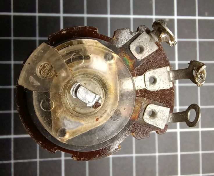
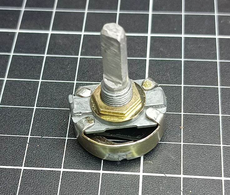
Here is one of the potentiometers I started with. This one is probably at least 30 years old. The grease had hardened and the shaft had become hard to turn. It was also of a resistance value that I thought I would be unlikely to use. Otherwise it seemed like good quality so it became a donor.

The next thing to do was to bend the lugs back and pop off the bottom casing.

I binned the bottom case, though in hindsight I might’ve been better off drilling a hole in it and mounting the sensor PCB directly on to it. More about that later in the post.
The shaft still has the board with the resistive track and brushes attached. They need to go, but the clear disk part needs to stay.
I broke off the board by twisting it with a pair of needle-nose pliers.
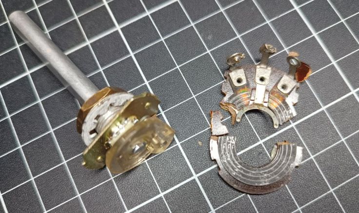
The wipers are still there. They had to come off too. This was a small challenge.

Finally it’s off.

With all the unnecessary bits gone, the pot was still annoyingly stiff to turn. I gave it a good clean with WD40. I know it is not a lubricant, but I thought it would soften up the old grease. After much turning it improved and I added some lighter oil and turned it some more. Beware if you do this. When I added the WD40 to the third one I made it loosened more than I wanted.

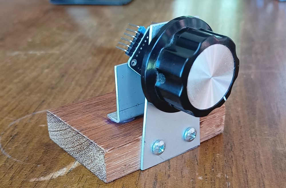
The sensor comes with a suitable magnet. I used hot melt glue to mount it onto the end of the shaft. I had to reheat the glue a couple of times as it was more difficult to mount it centrally than anticipated. Here it is, mounted on a piece of aluminium I’m using as the front panel of my test rig.

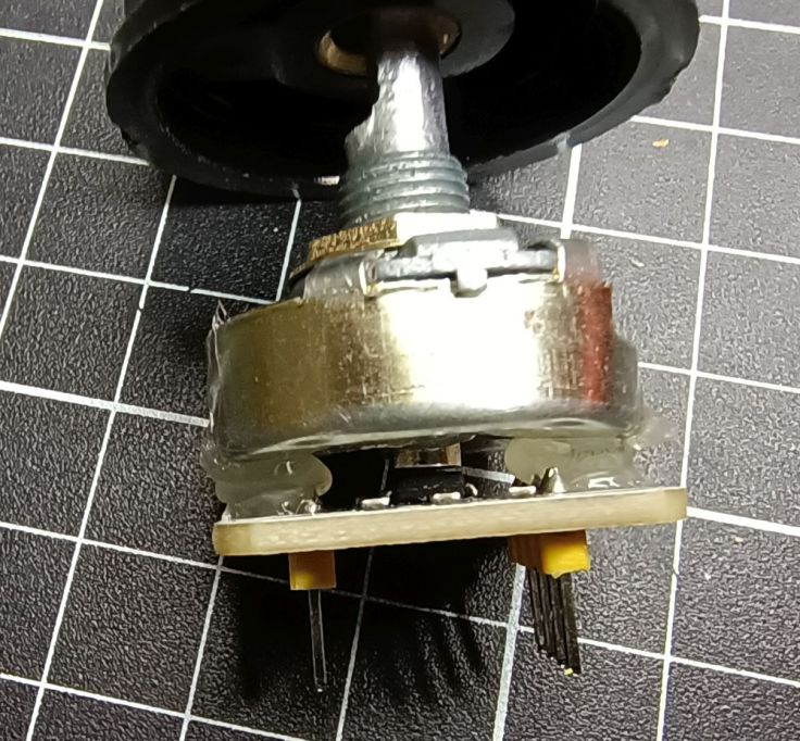
Here is a side view: the sensor is hot-glued to another bit of aluminium. The magnet needs to sit centred over the IC, about 1–3 mm away.

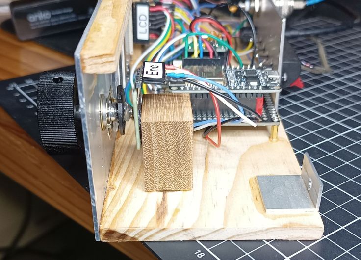
In the Tuning Wheel project I mounted the sensor module on a PCB attached to a block of wood.

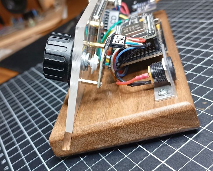
In this project the module is mounted to the front panel using brass standoffs.
In this one the module is glued to a wooden block.
Using the potentiometer back
After making two of these and starting this post I realised I may have missed a trick by not using the back of the potentiometer to mount the sensor. I went savaging through the old food packets and other garbage in the bin but couldn’t find it, so I started again with another donor potentiometer.
I removed the back.

I carefully marked the centre using a centre square and then drilled a hole… not in the centre. This was much harder to do than I expected. It was difficult to hold it without bending the sides. I had to finish the hole with a round file.
I also tapped the bit back at the back top. This bit is punched in and it stops the pot from being rotated continuously.

Next the board and wiper contacts were removed. I had to cut off the protruding bit from the back of the black plastic part as it was in the road. It came off easily with side cutters.

Here it is with it removed. It was at this point I wondered if I should have done that. The wipers affect the smoothness and are worth removing. However, the board also acts as a spacer between the front housing and the back. Oh well, too late now.

Next I cleaned and assembled it back together. Because the board had been removed the tabs folded lower down.
I glued the magnet on with hot melt glue.
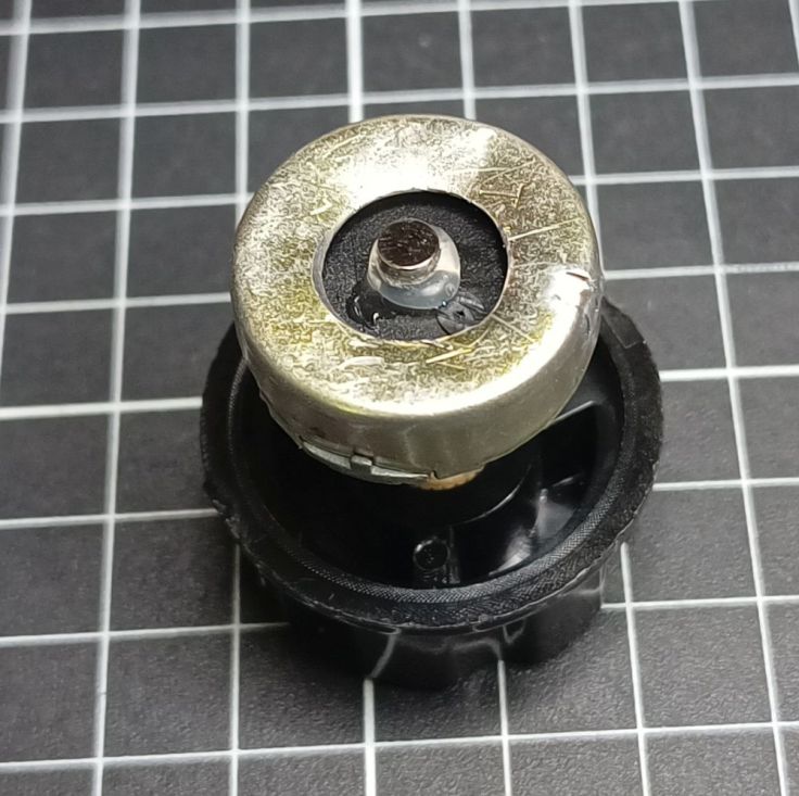
And then glued the sensor onto the bottom. For this one I used an AS5600 sensor. Look at it! You would never know it is not a commercial product…. at least not when it is eventually mounted in an enclosure 🙂
It was more fiddly and tricky using the pot bottom than I expected, but still seems like a worthwhile method.
Want to know more?
Curious to see where this is going? Have a look at these posts:
- Building a Tuning Wheel For PC SDR Radio Using an Angle Sensor, and
- Converting a Potentiometer For Use With a Magnetic Rotary Encoder
Got ideas or better methods? Please let me know.

Leave a comment