
I have a soft spot for rotary encoders. They are so simple, yet work so well as an interface. I have mostly used the cheap mechanical quadrature rotary encoders that are sold on modules. However, there are a couple of projects that I’m interested in where these are not ideal. The first is the tuning dial of a Si4732 based radio and the other is for a tuning knob for SDR software on a PC.
Neither of these need detents, in fact it may be better if they didn’t have any as that would allow it to turn more freely. They do need to be able to handle constant use, which is in contrast to the cheap encoders. Finally, it would be helpful if the resolution could be changed.

Experimenting with an angle sensor
There are optical encoders that would probably be ideal, but I wanted to experiment. I was impressed with the AS5600 angle sensor module that I used in my wind vane project and started thinking about what else I could use one for. These modules output a number based on the orientation of a magnet above the sensor IC. I can’t see it as a drop in replacement for a quadrature encoder, but they do seem easy enough to use and could work with code changes.
Differences to a quadrature encoder
As far as I can tell there are some significant differences between these sensors and a quadrature encoder. The module has to be polled to monitor for changes. I can’t see how it could be set up to work with interrupts as can be done with a quadrature encoder. This is not necessarily as bad as it sounds as when it is polled it responds with the new setting, so in a sense it is not missing changes.
While interrupts are not an option, the polling could be done using an RTOS task with an ESP32. This way the polling continually runs in a background task. I tested code for that which worked, but I won’t go into that here. For this code I’m keeping it simple and just using regular polling.
Tuning control for SDR radio
I thought about just doing a post with sample code, but after consideration I thought it would be better to actually use it in a project and see how it behaves in practice. I decided on a tuning knob for PC SDR software that behaves as a mouse wheel. I consulted ChatGPT and it helpfully provided some code and with some back and forth and tweaking, it worked.
Options for the rotating part
A good thing, or a downside depending on your point of view is that you can combine the module with other items for the shaft and knob. I’ve been thinking about what I could use. The main criteria I wanted
- Something with a shaft that I could mount a knob
- A method of fastening the body to the project
- The ability to place a magnet at the back end of the shaft so it rotates above the sensor
Initially I thought about using an old motor. I have lots of these, but the ones I have didn’t seem easy to convert. I tried a few other methods. A bearing and bolt didn’t work as well as expected. I tried to modify old hard drive motors, but most, particularly newer ones don’t have the end of the shaft exposed to mount the magnet.
Old potentiometer
I had an old burnt-out potentiometer that I had pulled apart. The shaft was quite stiff. I gave it a bit of a flush out with WD40 and then a drop of oil and it then turned quite freely. This method not only met my three criteria, but old pots are also easy to find.

Code
My goals for this project were to test the performance of the AS5600 as a replacement for a rotary encoder. I also want to learn more about using ChatGPT for coding, so I didn’t write the code myself. It was mainly generated by ChatGPT. I asked ChatGPT “Can you add comments to show what each line does and also how to set the resolution” and it added in lots of helpful comments. This should make it easier for us to follow.
While there is at least one library for the AS5600, including the Rob Tillaart AS5600 library, I deliberately asked ChatGPT to not use a library in this case.
/*
Mouse Jog Wheel using AS5600 and ESP32-S3 Super Mini
====================================================

Generated with the assistance of OpenAI's ChatGPT

This program is free software: you can redistribute it and/or modify it under the
terms of the MIT License https://opensource.org/license/mit

THE SOFTWARE IS PROVIDED "AS IS", WITHOUT WARRANTY OF ANY KIND

Connections (AS5600 → ESP32-S3)
-------------------------------
AS5600	    ESP32-S3 SuperMini
VCC	        3.3V
GND	        GND
SDA	        GPIO 8
SCL	        GPIO 9
*/

#include <Wire.h>             // I2C library to talk to the AS5600 sensor
#include "USB.h"              // Core USB support for ESP32-S3
#include "USBHIDMouse.h"      // HID Mouse class (lets the board act as a USB mouse)

// --- AS5600 Constants ---
#define AS5600_ADDRESS 0x36   // I2C address of the AS5600
#define RAW_ANGLE_MSB  0x0C   // Register for the raw angle (MSB first)

// --- I2C Pin Definitions (ESP32-S3 SuperMini) ---
#define SDA_PIN 8             // Yellow wire → SDA
#define SCL_PIN 9             // Blue wire → SCL

USBHIDMouse Mouse;            // Create a USB mouse object (for scroll events)

int lastAngle = 0;            // Stores the last measured angle
int accumulator = 0;          // Collects partial movements until a full "step" is reached

// --- Resolution / Sensitivity ---
// stepThreshold = number of raw angle units that equals ONE scroll step
// - AS5600 gives 0–4095 counts per revolution (12-bit resolution).
// - 4096 / stepThreshold = number of scroll steps per revolution.
// Example values:
//   64   → 64 counts per step → 64 steps per rev (≈11.25° each)
//   32   → 32 counts per step → 128 steps per rev (≈2.8° each, more sensitive)
//   128  → 128 counts per step → 32 steps per rev (≈22.5° each, less sensitive)
const int stepThreshold = 64;

void setup() {
  Wire.begin(SDA_PIN, SCL_PIN);   // Start I2C on chosen pins
  delay(100);                     // Wait for AS5600 to power up

  USB.begin();                    // Start USB system
  Mouse.begin();                  // Initialize the HID mouse

  lastAngle = readAngle();        // Read initial angle to set baseline
}

void loop() {
  processRotation();              // Check sensor and send scroll if moved
  delay(5);                       // Small delay for stability/responsiveness
}

// --- Handle movement and generate scroll events ---
void processRotation() {
  int currentAngle = readAngle();                                // Read new angle
  int delta = calculateAngleDifference(lastAngle, currentAngle); // Find change since last reading
  accumulator += delta;                                          // Add to movement accumulator
  lastAngle = currentAngle;                                      // Update stored angle

  // Enough movement for a scroll "up" event
  while (accumulator >= stepThreshold) {
    Mouse.move(0, 0, 1);   // Send scroll up (third param = wheel movement)
    accumulator -= stepThreshold;
  }

  // Enough movement for a scroll "down" event
  while (accumulator <= -stepThreshold) {
    Mouse.move(0, 0, -1);  // Send scroll down
    accumulator += stepThreshold;
  }
}

// --- Read 12-bit angle from AS5600 ---
int readAngle() {
  Wire.beginTransmission(AS5600_ADDRESS);
  Wire.write(RAW_ANGLE_MSB);           // Tell AS5600 we want angle register
  Wire.endTransmission();

  Wire.requestFrom(AS5600_ADDRESS, 2); // Ask for 2 bytes
  while (Wire.available() < 2);        // Wait until they arrive

  int high = Wire.read();              // MSB
  int low = Wire.read();               // LSB
  return ((high << 8) | low) & 0x0FFF; // Combine to 12-bit angle (0–4095)
}

// --- Calculate shortest angle difference, accounting for wrap-around ---
int calculateAngleDifference(int fromAngle, int toAngle) {
  int diff = toAngle - fromAngle;
  if (diff > 2048) diff -= 4096;       // Handle wrap-around forward
  else if (diff < -2048) diff += 4096; // Handle wrap-around backward
  return diff;
}
Parts
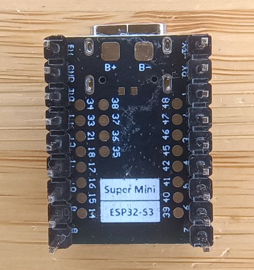
I’ve recently got my first ESP32-S3 Super Mini microcontroller module. These modules are inexpensive. Another benefit is these have the ability to act as a Human Interface Device (HID) like a keyboard or mouse because the ESP32-S3 chip itself supports the HID protocol.
I got this one from AliExpress. Just be careful when clicking on the link as it defaults to the C3 SuperMini which doesn’t work as a USB device so be sure to select the S3 SuperMini module. The seller was selling these for AU$5.89 (US$3.90) when I purchased them. Check other listings as they are often on special.

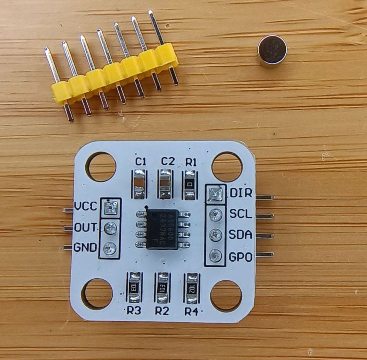
I also purchased the AS5600 Angle Sensor Module from AliExpress. I purchased two for AU$3.73 (US$2.47). This special has ended as well, but you should be able to find others for this or a lower price.
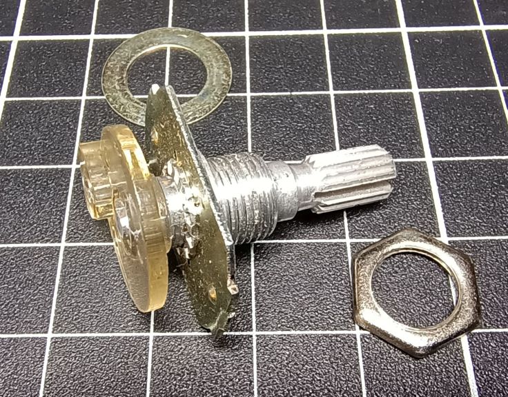
As mentioned earlier, the shaft for the magnet and knob comes from an old potentiometer. I disassembled it until all that remained was the parts in the photo.
I tried a couple of knobs. It has a significant impact of the overall feel. I ended up using an old Bakelite knob. The part of the knob you hold is 42mm diameter. It also has some weight and it feels very smooth to use. I came across some listings on AliExpress for knobs like this, but at AU$15.39 it seemed a bit much for a test.
Circuit diagram
The circuit is very simple as there are only the two modules. These are connected together by four wires. The USB socket on the ESP32-S3 is used to both upload the program and as the connection to the PC as the tuning wheel.

The build
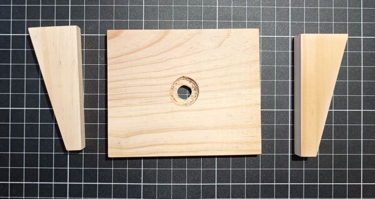
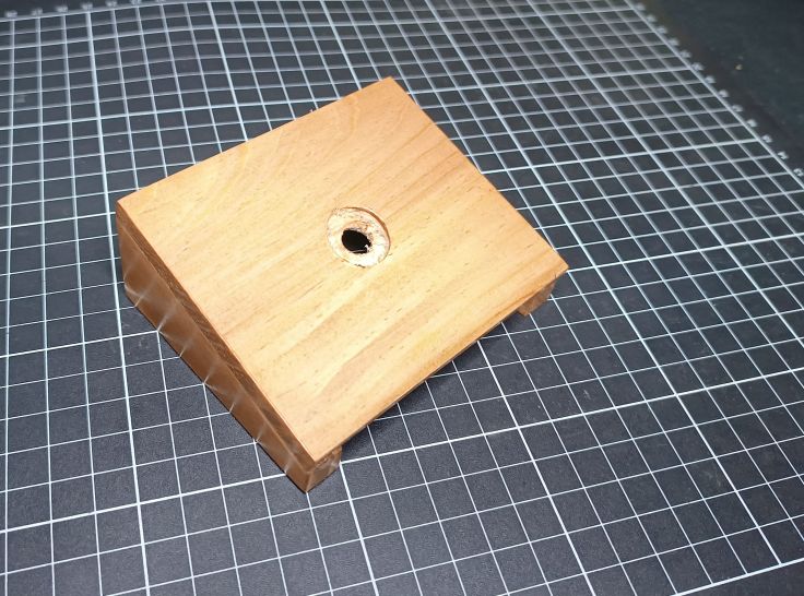
I housed the project under a simple stand made from 3 pieces of pine. I have the tools to make quick accurate cuts so I thought this would be easy, but the timber for the top was a bit thick for the thread of the potentiometer so I had to drill a larger shallow hole for the potentiometer nut. It would probably be easier just to use a regular project box.
I glued the timber parts together.
The AS5600 sensor comes with a magnet. I glued it to the shaft of the potentiometer shaft with hot melt glue. This is not a regular circular magnet. Instead of having north on one flat face and south on the other, they’re polarised around the edges; north on one round side, south on the other.

Connections were made between the boards. The negative wire goes from GND on the ESP32-S3 to both the GND and DIR connections on the AS5600. The DIR connection is used for the rotation direction. It is connected to ground rather than leaving it floating.

Here is a shot from the other side.

The ESP32-S3 board is glued to the timber and the AS5600 to a scrap piece of PCB. Both were glued using hot melt glue.

A small block of wood was glued to the housing for mounting the AS5600 board. It is important to have the magnet directly over the sensor and within 1 to 3mm of it.

The PCB is fastened with a single screw to allow for a bit of adjustment.

Uploading code
I had some trouble getting the code to upload using the Arduino IDE. I have used ESP32 modules before, but not this one. This page has more info about the module. I had to set these settings in the tools menu to these options:
- USB CDC On Boot → Enabled
- USB DFU On Boot → Disabled
- Arduino Runs On → Core 1
- Upload Mode → UART0 / Hardware CDC (if you have trouble flashing, try UART0 first)
- USB Mode → TinyUSB (best for HID like mouse/keyboard/gamepad)
Calibration
One of the perks of the AS5600 compared to a cheap encoder is that you can easily change its resolution. The chip gives you 4096 steps per full rotation, and in the code a constant called stepThreshold controls how many of those steps make up a single movement. In other words, tweak stepThreshold and you tweak the sensitivity. The comments in the code have more info about this.
A note about onboard LEDs
When it is running two LEDs on the EDSP32-S3 are illuminated. The red LED is a power LED. The other is a blue LED that constantly flashes. This confused me for too long until I found this. The short answer is it is a battery charge indicator. As I had no battery connected, blinking is normal.
- Charging → LED on
- Battery connected → LED off
- No battery → LED blinks
Result
It behaves the same as using the mouse scroll wheel, so you shouldn’t expect more features than that. However, it is much nicer to use than expected. It is extremely smooth to turn. Giving it a flick makes it spin a couple of revolutions. Having the knob rotate clockwise and anticlockwise is also more natural feeling than a mouse wheel. While I don’t use SDR radio much, I will be keeping this project and will be looking for more uses for it and using AS5600 modules in other projects.
If you decide to build one yourself, I’d love to hear how it turns out. Got ideas for improving the design, or built something similar? Drop a comment and let me know.

Leave a comment