
I’ve had an interest in detecting lightning for many years. I remember reading an article about Benjamin Franklins lightning experiments back in the 80’s or early 90’s. I thought the article was in an issue of Electronics Australia, but I have not been able to locate it. Ben Franklin is fairly well known for flying a kite in a thunderstorm as part of his electricity experiments, but his lightning bells are probably not as well known. He had set up a lightning rod on the top of his house and run a wire through a glass tube to some bells and from those to an iron spear of a pump. The page For Whom the Bells Toll has his account. It is short and well worth a read. This is part of his report “…sometimes in very large, quick cracks from bell to bell, and sometimes in a continued, dense, white stream, seemingly as large as my finger, whereby the whole staircase was enlightened with sunshine…” Must have been both spectacular and terrifying. Definitely not something that should be tried at home.
Choosing a design
Recently I’ve come across two designs that I thought were interesting. The first in a project by Mirko Pavleski; Sensitive Arduino Lightning detector with homemade sensor
There is also this page of hackster.io.
It uses a TA7642 AM radio IC, which is similar to the ZN414, MK484 and YS414. The ZN414 is a 3 pin single-chip AM radio. Looking like a transistor the IC is simple to use, runs on 1.5V and doesn’t require many external components. The datasheet says it convers 150kHz to 3MHz. I’ve built a few radios using it and although the performance of my builds wasn’t great it does hold a special place for me. If you are interested in this method, a Google search for TA7642 lightning detector returns a lot of projects.
The other design uses modules based around the AS3935 Franklin Lightning Sensor IC. I was pleasantly surprised to discover there is a dedicated chip for lightning detection. A benefit of using this IC is that “…. provides an estimation on the distance to the head of the storm. The embedded lightning algorithm checks the incoming signal pattern to reject the potential man-made disturbers.“
Sparkfun boards
As much as the first one was tempting and cheapest as I already had some MK484 ICs, the ability to filter out other other disturbances made the second designs more enticing. There are at least two different modules that use this IC. One is the SparkFun Lightning Detector – AS3935. Sparkfun has created an Arduino library for it.
Aliexpress boards
There are another group of modules with similar names; MCU-3935, JMCU-3935 WCMCU-3935 CJMCU-3935 are some that I’ve seen online. All use the AS3935 IC. As I was already planning an order with Aliexpress I ordered this one.
This is the front. At the top is a coil

The back doesn’t have any components but does have the pin labels.
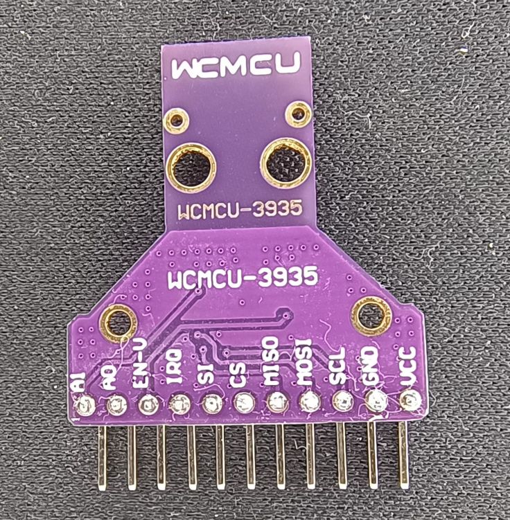
The one I received is marked WCMCU-3935, but in the ad it has JMCU-3935. I don’t know that it matters, but one thing I learned after receiving it is that some people have reported that some of these boards have incorrect value capacitors that affect tuning. I haven’t measured the value of those on mine, but I was able to calibrate it so I think it is ok.
SPI or I2C
The board supports both. Looking at other peoples projects and consulting with ChatGPT it seemed like some people had issues using it with I2C so I went with SPI and didn’t have any issues. I didn’t try I2C.
Capacitors and calibrating the frequency
The IC with the coil and capacitors is designed to operate just below the AM broadcast band at 500kHz. At a basic level it is not that different than listening to a quiet spot with a radio on the lower AM band and hearing the static generated by lightning. I guess this is why some people are using the TA7642 AM radio IC.
While the modules should be close to the 500kHz frequency when purchased, they can be tuned closer by switching inbuilt capacitors within the IC in or out. This is where it appears that some boards have an issue. It seems they have external capacitors that are too far from what is needed and the inbuilt capacitors cannot compensate enough. I found some info about that here and here.
The datasheet says the frequency only needs to be within 3.5% of 500kHz which is worth remembering when tuning. That’s 482.5kHz to 517.5kHz, so not that critical.
I found tuning a little confusing, so I’ll go into a bit of detail now that I think I understand it. The procedure I used was to install and follow the Sparkfun library Example3_Tune_Antenna_SPI sketch.
There are inbuilt capacitors in the sensor IC that can be switched in by uncommenting and changing the value in this line:
lightning.tuneCap(8);
It accepts values to 120pF in steps of 8pF: 8, 16, 24, 32, 40, 48, 56, 64, 72, 80, 88, 96, 104, 112, 120.
The IRQ pin of the sensor is normally used to notify the microcontroller when the sensor detects lightning, noise or a disturbance. The tuning sketch, however, sets the IRQ pin to oscillate at a frequency based on the circuits tuned frequency. Rather than connecting the IRQ pin to the microcontroller, connect it to a frequency counter. The IRQ pin doesn’t actually oscillate at the tuned frequency, rather a fraction of that frequency. That fraction is set using readDivRatio. By default it is 16, but can also be set to 32, 64, or 128. So with the readDivRatio set to 16 a frequency of 31.25kHz will be output on the IRQ pin when the oscillator is running at 500kHz.
I uncommented the lightning.tuneCap(8); line in the tuning sketch. Then I uploaded and ran the sketch, checked the output frequency with my oscilloscope and multiplied the frequency displayed by the division ratio, in my case by 16 to get the tuned frequency. Then I updated the value in that line, uploaded again and measured the frequency. These are some of the results I got:
tuneCap(8) = 32.0978 x 16 (division ratio) = 513.5648 kHz
tuneCap(32) = 31.7876 x 16 (division ratio) = 508.6016
tuneCap(64) = 31.3776 x 16 (division ratio) = 502.0416
tuneCap(72) = 31.2759 x 16 (division ratio) = 500.4144
tuneCap(80) = 31.1771 x 16 (division ratio) = 498.8336
tuneCap(96) = 30.9882 x 16 (division ratio) = 495.8112
A value of 72 gets it almost spot on 500Hz. Now all I need is to include lightning.tuneCap(72); in sketches that use that module.
While I used an oscilloscope to measure the frequency, I also have a cheap ANENG AN8008 multimeter that can measure frequency. I tried it and while it only displayed two decimal places it would have been fine for this purpose.
Measuring the frequency with an ANENG multimeter.

Construction
I used a ESP32 module mounted on a small protoboard with PCB screw terminals for power and the module connections.
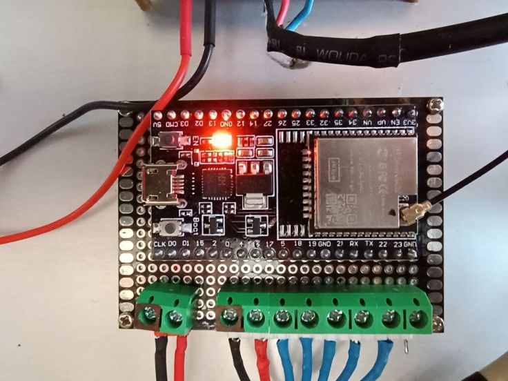
The ESP32 and some other ESP32 projects are mounted in an old PC case. While it may appear to be powered by a PC power supply, it is actually powered by a 5V Mean Well power supply.

The sensor module is mounted in an old project case I had. It is connected to the ESP32 by about 3.5 metres of Cat5 network cable. I did this to keep the sensor away from the ESP32 and other electrical items that may generate noise. Using twisted pairs is probably not ideal, but I needed 7 wires between the sensor and MCU and this was the best I had.
The inside of the sensor box.

The outside of the box,

Testing
Testing was somewhat challenging due to my inability to summon lightning. I have a cheap samba click flame gas lighter. It’s one of those lighters that generate a spark by compressing a piezoelectric crystal. I found that clicking it within a couple of centimetres of the sensor it was detected as lightning. I have an old VFD calculator that when held up to the the sensor detects it as noise. I couldn’t find a way of generating other ‘disturber’ events. I have a rechargeable USB arc lighter that I thought would trigger an event, but curiously it didn’t generate any at all.
This calculator created ‘noise’ and the lefthand lighter ‘lightning’ but the second lighter didn’t trigger any events.

Tweaking other settings
As well as the setting the inbuilt capacitors to tune the frequency, there are a few other settings. The second library example sketch Example2_More_Lightning_Features_SPI.ino.
I’ve tweaked a few settings to make it more sensitive as I have it set up in a fairly RF quiet area, but I don’t think I have it set optimally yet.
Code
I recommend starting with the examples in the Sparkfun library. I’ve included my code below, but it won’t work by itself. This code is only for a sender unit that sends an “I’m alive” message every 10 minutes and a message whenever there is an event to a receiver using ESPNOW. The receiver is based on the sketch in Customizing the Random Nerd Tutorials ESP-NOW Web Server Sensor Dashboard. I’ve included it here just for completeness.
/*
  WEATHER STATION LIGHTNING SENSOR SENDER
  =======================================

  Reads data from S3935 lightning sensor and sends to receiver using ESPNOW

*/

#include <SPI.h>
#include <Wire.h>
#include "SparkFun_AS3935.h"
#include <esp_now.h>
#include <esp_wifi.h>
#include <WiFi.h>

// Set your Board ID (ESP32 Sender #1 = BOARD_ID 1, ESP32 Sender #2 = BOARD_ID 2, etc)
#define BOARD_ID 5

// For lightning detector
#define INDOOR 0x12
#define OUTDOOR 0xE
#define LIGHTNING_INT 0x08
#define DISTURBER_INT 0x04
#define NOISE_INT 0x01

//MAC Address of the receiver
uint8_t broadcastAddress[] = {0x00, 0x00, 0x00, 0x00, 0x00, 0x00}; // Set to the address of the receiver

//Structure for send data
typedef struct struct_message_lightning {
  unsigned int sensorId;
  unsigned int readingId;
  int eventType;
  byte distance;
  long energy;
  //int batteryVoltage;
  bool lastCallbackstatus;
} struct_message_lightning;

esp_now_peer_info_t peerInfo;

//Create a struct_message
struct_message_lightning lightningData;

int readingNum = 0;           // For storing reading number in RTC memory while asleep
bool lastCallback;            // For storing record of last callback outcome in RTC memory

unsigned long lastRegularSend = 0;                // Storing the time of the last alert sent
const unsigned long regularSendInterval = 600000; // Period for regular notifications - 10 minutes in milliseconds

// SPI
SparkFun_AS3935 lightning;

// Interrupt pin for lightning detection
const int lightningInt = 4;
// Chip select pin
int spiCS = 5; //SPI chip select pin (original sketch set to 10)

// Values for modifying the IC's settings. All of these values are set to their
// default values.
byte noiseFloor = 2;
byte watchDogVal = 2;
byte spike = 2;
byte lightningThresh = 1;

// This variable holds the number representing the lightning or non-lightning
// event issued by the lightning detector.
byte intVal = 0;

// callback when data is sent
void OnDataSent(const uint8_t *mac_addr, esp_now_send_status_t status) {
  Serial.print("\r\nLast Packet Send Status:\t");
  Serial.println(status == ESP_NOW_SEND_SUCCESS ? "Delivery Success" : "Delivery Fail");
}

void setup()
{
  // Lower CPU frequency to save power
  setCpuFrequencyMhz(40);

  // When lightning is detected the interrupt pin goes HIGH.
  pinMode(lightningInt, INPUT);

  Serial.begin(115200);
  Serial.println("AS3935 Franklin Lightning Detector");

  SPI.begin(); // For SPI
  if( !lightning.beginSPI(spiCS) ) {
    Serial.println ("Lightning Detector did not start up, freezing!");
    while(1);
  }
  else {
    Serial.println("Schmow-ZoW, Lightning Detector Ready!");
  }

  lightning.tuneCap(72);  // Calibrate oscillator

  lightning.maskDisturber(true);
  lightning.setIndoorOutdoor(OUTDOOR);
  lightning.setNoiseLevel(noiseFloor);
  lightning.watchdogThreshold(watchDogVal); ;
  lightning.spikeRejection(spike);
  lightning.lightningThreshold(lightningThresh);

  Serial.println("=======================================================");

}

void loop()
{

  // Check if it's time to run the 10-minute function
  unsigned long currentMillis = millis();
  if (currentMillis - lastRegularSend >= regularSendInterval) {
    lastRegularSend = regularSendInterval;

    // Set values to 0 and send data
    lightningData.eventType = 99;
    lightningData.distance = 0;
    lightningData.energy = 0;

    sendData();

    lastRegularSend = currentMillis;

    Serial.println("-------------------------------------------------------");
  }

  if(digitalRead(lightningInt) == HIGH){
    // Hardware has alerted us to an event, now we read the interrupt register
    // to see exactly what it is.
    intVal = lightning.readInterruptReg();
    lightningData.eventType = intVal;
    //lightningData.eventType = lightning.readInterruptReg();
    if(intVal == NOISE_INT){
      Serial.println("Noise.");
    }
    else if(intVal == DISTURBER_INT){
      Serial.println("Disturber.");
    }
    else if(intVal == LIGHTNING_INT){
      Serial.println("Lightning Strike Detected!");
      // Lightning! Now how far away is it? Distance estimation takes into
      // account previously seen events.
      byte distance = lightning.distanceToStorm();
      lightningData.distance = distance;
      Serial.print("Approximately: ");
      Serial.print(distance);
      Serial.println("km away!");

      // "Lightning Energy" and I do place into quotes intentionally, is a pure
      // number that does not have any physical meaning.
      long lightEnergy = lightning.lightningEnergy();
      lightningData.energy = lightEnergy;
      Serial.print("Lightning Energy: ");
      Serial.println(lightEnergy);

    }
    sendData();
    lastRegularSend = currentMillis;
    Serial.println("=======================================================");
  }
}

void sendData() {

  // Speed up processor for wifi module
  setCpuFrequencyMhz(80);

  // Set device as a Wi-Fi Station and set channel
  WiFi.mode(WIFI_STA);

  int32_t channel = 6; // Or use this to set to predetermined channel

  //WiFi.printDiag(Serial); // Uncomment to verify channel number before
  esp_wifi_set_promiscuous(true);
  esp_wifi_set_channel(channel, WIFI_SECOND_CHAN_NONE); // Sets to predetermined channel
  esp_wifi_set_promiscuous(false);
  //WiFi.printDiag(Serial); // Uncomment to verify channel change after

  // Init ESP-NOW
  if (esp_now_init() != ESP_OK) {
    Serial.println("Error initializing ESP-NOW");
    return;
  }

  // Once ESPNow is successfully Init, we will register for Send CB to
  // get the status of Transmitted packet
  esp_now_register_send_cb(OnDataSent);

  // Register peer
  memcpy(peerInfo.peer_addr, broadcastAddress, channel);
  peerInfo.encrypt = false;

  // Add peer
  if (esp_now_add_peer(&peerInfo) != ESP_OK){
    Serial.println("Failed to add peer");
    return;
  }

  readingNum++; // Update reading number

  lightningData.sensorId = BOARD_ID;
  lightningData.readingId = readingNum;
  lightningData.lastCallbackstatus = lastCallback;


  // Print values for debugging
  Serial.printf("Board ID:  %d \n", lightningData.sensorId);
  Serial.printf("Reading number: %d \n", lightningData.readingId);
  Serial.printf("Event type: %d \n", lightningData.eventType);
  Serial.printf("Lightning distance: %d \n", lightningData.distance);
  Serial.printf("Lightning energy: %d \n", lightningData.energy);
  //Serial.printf("Battery voltage: %d \n", lightningData.batteryVoltage);
  Serial.printf("Last callback status: %s \n", lightningData.lastCallbackstatus ? "Received" : "Failed");
  Serial.println();

  // Send message via ESP-NOW
  esp_err_t result = esp_now_send(broadcastAddress, (uint8_t *) &lightningData, sizeof(lightningData));
  if (result == ESP_OK) {
    lastCallback = true;
    Serial.println("Sent with success");
  }
  else {
    lastCallback = false;
    Serial.println("Error sending the data");
  }

  // Disable ESPNOW and radio
  esp_now_deinit();      // Disable ESP-NOW
  WiFi.mode(WIFI_OFF);   // Shut down Wi-Fi to save power

  // Return processor to slower lower power state
  setCpuFrequencyMhz(40);

}
This is how the receiver displays it on a web page. At the top is the count of the days strikes and below the last 20 events (over all days) are listed.

Use
So far we have only had two small electricals storm that didn’t have much lightning. Some of the lightning was detected but not all. The image above shows what was detected during the last one. I’m estimating that it only displayed about 30% of the strikes. It may be good at giving an idea how far away a storm is, but mine is not good at showing the count of strikes. Unfortunately, it will probably be another 4 months before we get more electrical storms. I’ll need to do more tweaking and report back after that.
More info
This is a list of things that I found helpful:
- AS3935 Franklin Lightning Sensor IC datasheet
- SparkFun AS3935 Lightning Detector module
- Sparkfun’s Get Started with the SparkFun Lightning Detector
- Sparkfun’s AS3935 library
- Tasmoto page listing modules and info about them
- improwis.com page with info about the capacitor issue and board improvements to reduce noise
- The module I used
Title image
The title image was generated by ChatGPT from one of my photos. The other photos are my own slop.
Final Thoughts
While it’s taken some time to write this up I don’t feel I have added much of value. Perhaps it will give you ideas. Remember, I’m just a hobbyist so if you have any thoughts, see errors or just want to say hello, feel free to post a comment.
Update: 16 October 2025
We recently had our first storm pass through. There wasn’t a lot of strikes. This is what was listed on the sensors dashboard. The number of strikes is roughly the number we heard. The distance (in kms) shows the storm coming closer and then moving away. It was pleasing to confirm that it is working.


HI!Could you ad wiring diagram, how did you connect sensor to esp32? I am struggling with same sensor with esp32-c3 super mini with SPI. Only getting zeros out.
LikeLike
Hi, I’m using an ESP32 Dev module and the connections that I am using are:
Sensor – ESP32
——————
VCC – 3.3V
GND – GND
SCL – 18 (SCK)
MISO – 19 (MISO)
MOSI – 23 (MOSI)
CS – 5
SI – GND (select interface I2C/SPI)
IRQ – 4
Good luck with it.
LikeLike
“It is connected to the ESP32 by about 3.5 metres of Cat5 network cable.” – 3.5 m is too much, preferably max 30cm, otherwise the cable will act as an antenna
LikeLike
Yes, that would probably be ideal. Having said that, the SPI data is coming through without issue where I have it setup, but if I was doing it again I would aim to have them closer together.
LikeLike