
When working with a project on a breadboard I’ve been caught with the supply voltage on the breadboard not being what I expected which resulted in the project not working as expected.
To help prevent this I’ve bought some cheap mini 2 and 3 wire voltmeters. These sell for a couple of (AU) dollars. The 2 wire version just connects across the power source whereas, the 3 wire have an extra wire for measurement source.
2 and 3 wire versions
The 2 wire version I got was advertised as 0-30 volts. Other sellers have advertised them as 3-28 volts which seems closer to what I’m experiencing. With the ones I have the display begins to dim under 3 volts and stops completely at 2.5v. Still that’s ok for most of my needs. As the 2 wire version needs to draw power from the source it is measuring it means that it adds a load to the circuit. I measured a current draw of 18.5mA at 5 volts. I am only intending to use them for measuring the power rails so these should be ok that.
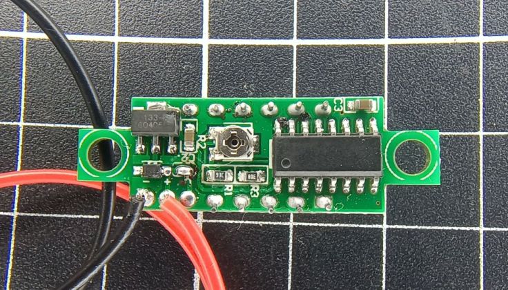
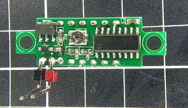
The 3 wire versions not only have dedication connections for power supply, they also have another connection for the voltage to be measured. The 3 wire versions are advertised as being able to measure 0-100 volts. I didn’t try them with high voltages and would not want to use them for that, but it measured down to 0.1V. I checked the current draw on the sense/measurement input and I got around of only 49uA. I measured the current draw on the power supply pins and got a surprising result. One measured 11mA and the other 16mA. I’m not sure why that is, but…
Quality
One of the 3 wire versions I bought has segment that does not light, at least usually. Sometimes I get a dim glow, but there is definitely something wrong with it.
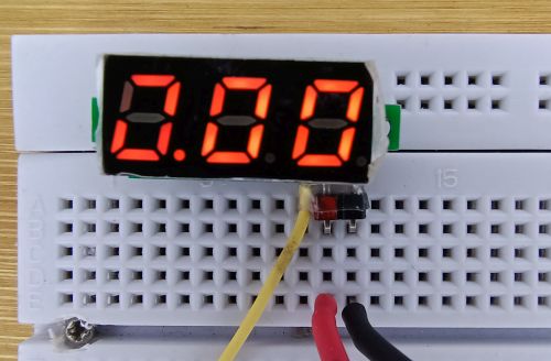
I tried reflowing connections, but it didn’t fix it. I had a similar issue with a slightly larger one some time back. I think where I went wrong is buying a cheap one from an ebay seller that didn’t specialise in electronics parts. I’m wondering if they may specialise in faulty parts 🙂
Converting for breadboard use
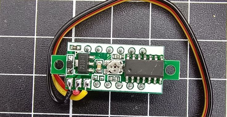
There are pads on the circuit board but they are not spaced with the usuall breadboard spacing. I was able to solder some 90 degree pin headers for power and added a small amount of red paint to the positive supply pin. I’m not sure they would go if the supply was reversed and I don’t want to involuntary try that.
For third wire I tried cutting one end of a breadboard jumper wire but in the end I didn’t use it. I quite like those wires but mine seem to be mostly insulation with only a very fine cable inside. I don’t know that the connection would have lasted long. I have some wire I pulled out of something that was better quality and used that. I soldered a header pin the the free end and placed some heatshrink over the connetction. On the meter end I placed some clear heatshink around all three connections for some strain relief.
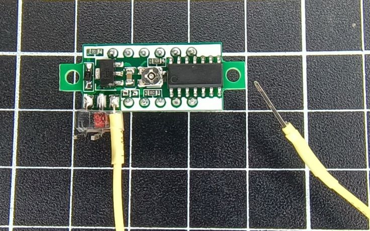
As the solder pads are so small, I don’t know how long they will last. I’ll have to be careful inserting them into breadboards to avoid breaking them.
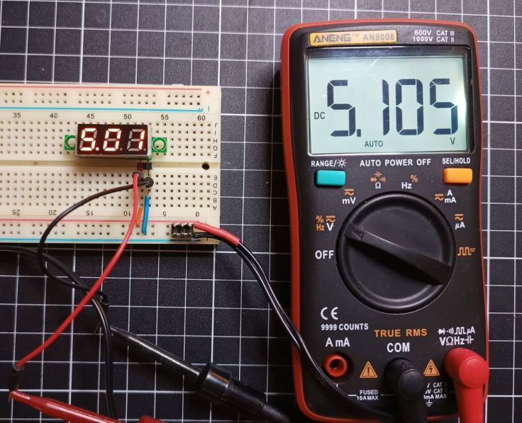
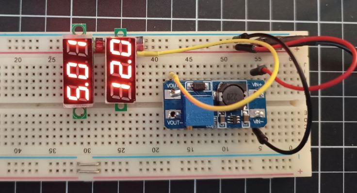
Here is a shot of them in use
Accuracy and adjustment
The modules are advertised as being adjusted in the factory. Comparing the reading with a couple of my multimeters it was about 0.1 volts different. By adjusting the small potentiometer on the back I got it slightly closer. While they display to two decimal places under 10 volts they appear to jump by at least .02 volts at a time
Finally
I don’t expect these are a replacement for a proper meter. I doubt they have much, if any protection circuitry. Their accuracy is not as high as a multimeter either. I’m still happy with them and intend to continue using them.
Is anyone else using these like this? How has your experience been? Anything I should be aware of?

Interesting… I didn’t even know these existed. Is there a part # on that IC on the back? I’m guessing it’s a 7-segment display driver chip and I’m curious what it takes for its data input. For the one where the display is dimly lit, you might try just reflowing the legs on that chip, if you haven’t already. If it’s indeed the driver, then it would likely be that the chip is bad or a cold solder joint.
LikeLike
Hi Ken, I did have a go at reflowing all the IC legs, but it is cramped for my soldering iron so I’m not sure I actually reflowed them all. I’ll give it another go. I have 4 and none of them have markings on the IC. I did find this page https://www.fbnews.jp/202112/w_trivia/ that has some info and they say it’s an ICL7136 A/D converter IC. I’m not sure if I’m misreading that article as it mentions 40 pins and mine don’t, but the images match up.
LikeLike
I use a couple of these just as a reminder of whether I’m using a 5/12/24V supply in an LED test fixture I built after an expensive mistake. AliExpress often has them (and their siblings that include a current pin) for dirt cheap and often marks them down as shipment filler.
Lipe Pro tip for strain relief: bend the wire back over the device (or just route it that way before soldering) and hot glue out of it.
LikeLike
Hi Robert, I used a couple of new ones the other day and I was reminded how the wire that comes with some of these is not particularly suitable where there is a bit of movement. I’ve recently purchased some of the silicon coated hookup wire from AliExpress and really like it. I replaced the wired on the voltmeters with some of that which improved it a lot. Hot glue sounds like a good idea too.
LikeLike
Good call. The other advantage of silicone wires, especially for test leads, is that they’re difficult to burn with a soldering iron or minor electrical mishap. Brush a jumper wire against a hot iron, and it’ll stink up the room for a day and leave your wire melted and often ruined. Silicone-coated wires are super flexible and almost impossible to burn/melt, so they’re great for this purpose.
In fact, it’s funny you mention this. Just a few hours ago, I unpackaged https://hardware.buspirate.com/cables/ for my little BusPirate 5 logic analyzer/scope/bus driver tool. I spent an unreasonable amount of time marveling at how flexible the silicone wires were, the details of the labels being readable—heck, of them being there at all—and just generally fawning at how well something could be built when price wasn’t the primary goal. It was such a rare feeling to delight in the quality of something we think of as so mundane. Sure, they’re more expensive than https://www.aliexpress.us/item/3256806607060662.html class products, but I’ll bet that I never have to debug a case of a broken wire inside the cable that makes my analyzer lie to me. That seems worth $9 in insurance.
Hot glue is quite effective for tacking down bodge and other stray wires. If you’re able to get it to stick to the top of your chips and you do later decide you need to set it free, you can usually get under the side with a knife and pry outward and just pop them off. If you blob it over your passives, it’s a lot harder to break them free.
I won’t keep chatting with you on your blog. I really just wanted to say “thank you” and to try to offer a helping hand up in a spot or two where I thought I could help. We’re about the same age and share a lot of background—I learned electronics because Dad ran a CB radio repair shop in our home, so I was always around this stuff and working with/on it even as a boy. I was in third grade when I built a power supply that I still use. I took the schematics from a Cobra CAM 89 (the desktop version of the Cam 88) and built mine from parts in the shop. Still runs great even now. I, too, am a big ESP32 nerd, and I have a handful of the DFPlayer modules, sensors, screens, and other parts that you’ve written about here.
If you ever want to reach me because you want a pen pal, myfirstnamemylastname atgmail will do the trick. Thank you for all your writing. I enjoyed it and learned plenty, too!
LikeLike
Thanks so much for the kind words and encouragement. I appreciate you taking the time to write. Sorry for the slow response, After 8 years I have finally replaced my laptop and it has not been quite as smooth as expected, particularly since I now have windows 11. I didn’t have many other people around me that were interested in electronics. Having a father running a CB radio repair shop would have been very cool.
Thanks for the offer to keep in touch, I’m not great at keeping up with correspondence, but I’ll definitely keep your email in mind. Don’t be surprised if an email turns up one day.
LikeLiked by 1 person