I recently came across a discussion on Reddit about MT6701 working modes, where someone referenced my earlier posts on using a magnetic sensor as a rotary encoder. That prompted me to look more closely at the different MT6701 modules currently available and how suitable they are as drop-in replacements for mechanical encoders.
What’s the point of the using a MT6701 module?
My goal is simply to replace low-cost mechanical rotary encoders in Arduino projects, particularly where they get heavy use with something more durable, without changing existing code.
The MT6701 can output standard quadrature (ABZ), so once configured it behaves like a typical encoder.
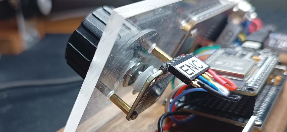
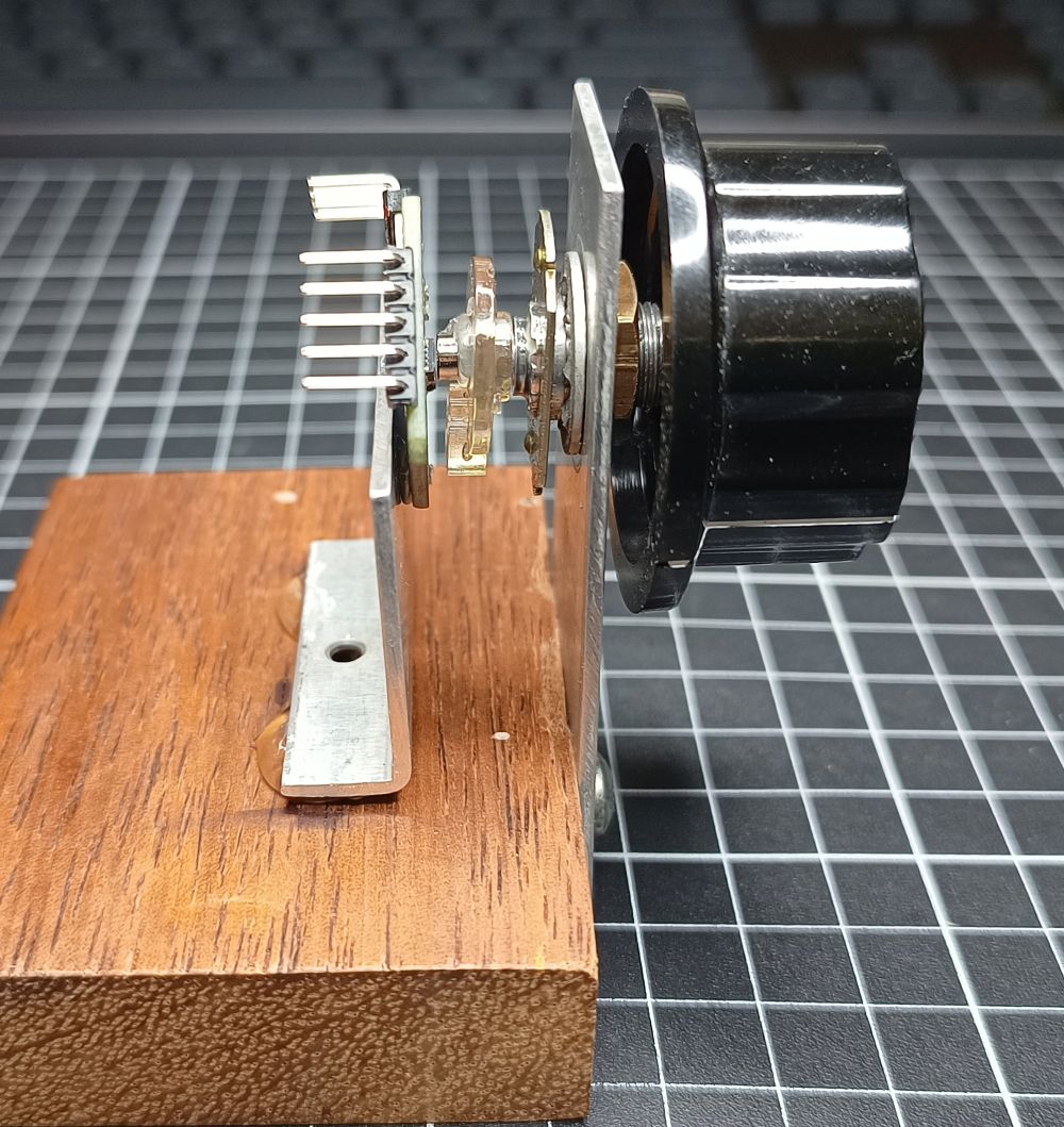
Mechanically, this still requires a rotating shaft and magnet. I’ve had good results reusing parts from a potentiometer to provide the shaft and mounting. This is my test setup.
Pins needed
As well as other modes the MT6701 supports:
- I²C mode → for configuration (EEPROM programming)
- ABZ mode → for quadrature encoder output
Key points:
- The same pins are reused between modes (e.g. SDA/SCL vs A/B)
- A mode pin selects between I²C and ABZ
- Some modules expose this cleanly; others do not
These are the pins used for programming and:
| I²C side for Programming | ABZ side For Encoder | Pin number SOP-8 Package | Pin number QFN-16 Package | Function |
|---|---|---|---|---|
| VDD | VDD | 1 | 13 | I²C programming mode: 5V I²C read or ABZ: 3.3 – 5V |
| Z | 8 | 8 | Digital Input/output Not used in this project | |
| SCL | A | 6 | 6 | I²C mode: SDA ABZ mode: Encoder Signal A |
| SDA | B | 7 | 7 | I²C mode: SCL ABZ mode: Encoder Signal B |
| GND | G | 4 | 16 | Ground |
| M | 2 | 14 | Selects ABZ (Encoder) or I²C (for programming in my case) mode. I²C mode: Leave unconnected ABZ mode: Connect to GND Connect to ground for ABZ Has built-in 200KΩ Pull-up Resistor |
There is more information about the versions and functions of the MT6701 in the MT6701 datasheet
Different versions
There are a number of different versions of the modules available. Some use the SOP-8 package, others the QFN-16 Package. Both the IC packages have the required pins.
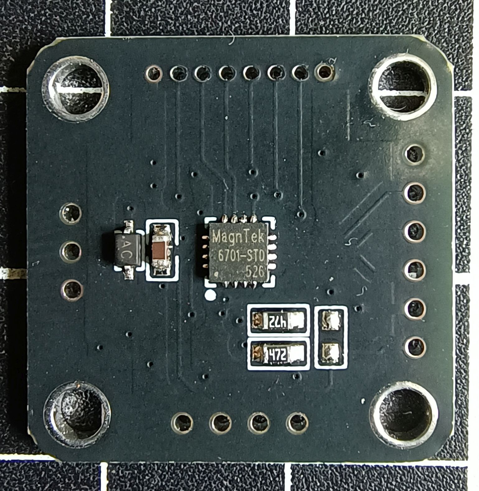
MT6701QT
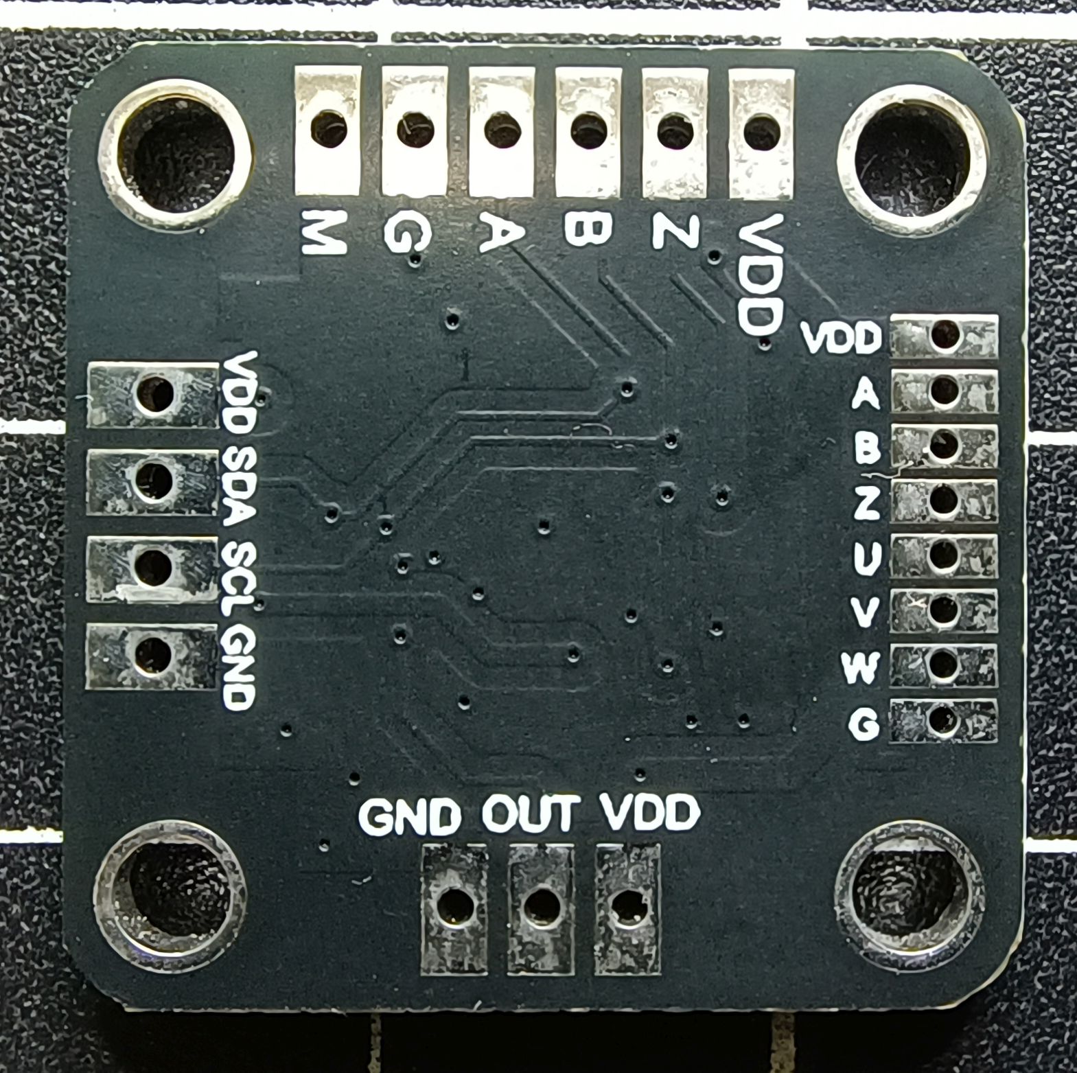
This is the original version I used. I bought my last lot from AliExpress here. They are currently AU$3.28 each, but cheaper in packs of 5 or 10. Its size is 23mm x 23mm. There are lots of pin holes on the PCB, but many are duplicates. It appears as thought pins required for each use case have been placed on a side of the board. For example I²C is one one side and ABZ ones or an another, even though the the I²C pins SDA and SCL are the same as A and B.
Programming the EEPROM
This is the easiest board to program. Connect the power, ground, SDA and SDL pins from the programming Arduino Nano to the pins on the module and upload the EEPROM programming code. To use as a rotary encoder connect the GND, VDD, A and B pins to your project and connect the Mode pin (M) to GND.
Pros
- Cheap (especially in bulk)
- Fully exposes all pins
- Easiest to configure and reuse
Cons
- 2 mm pin spacing (awkward for standard headers)
- Physically large
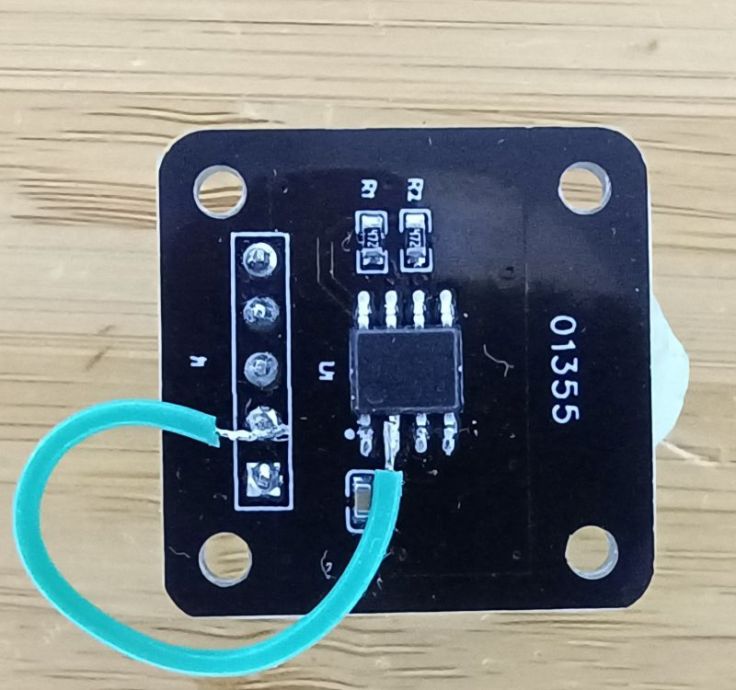
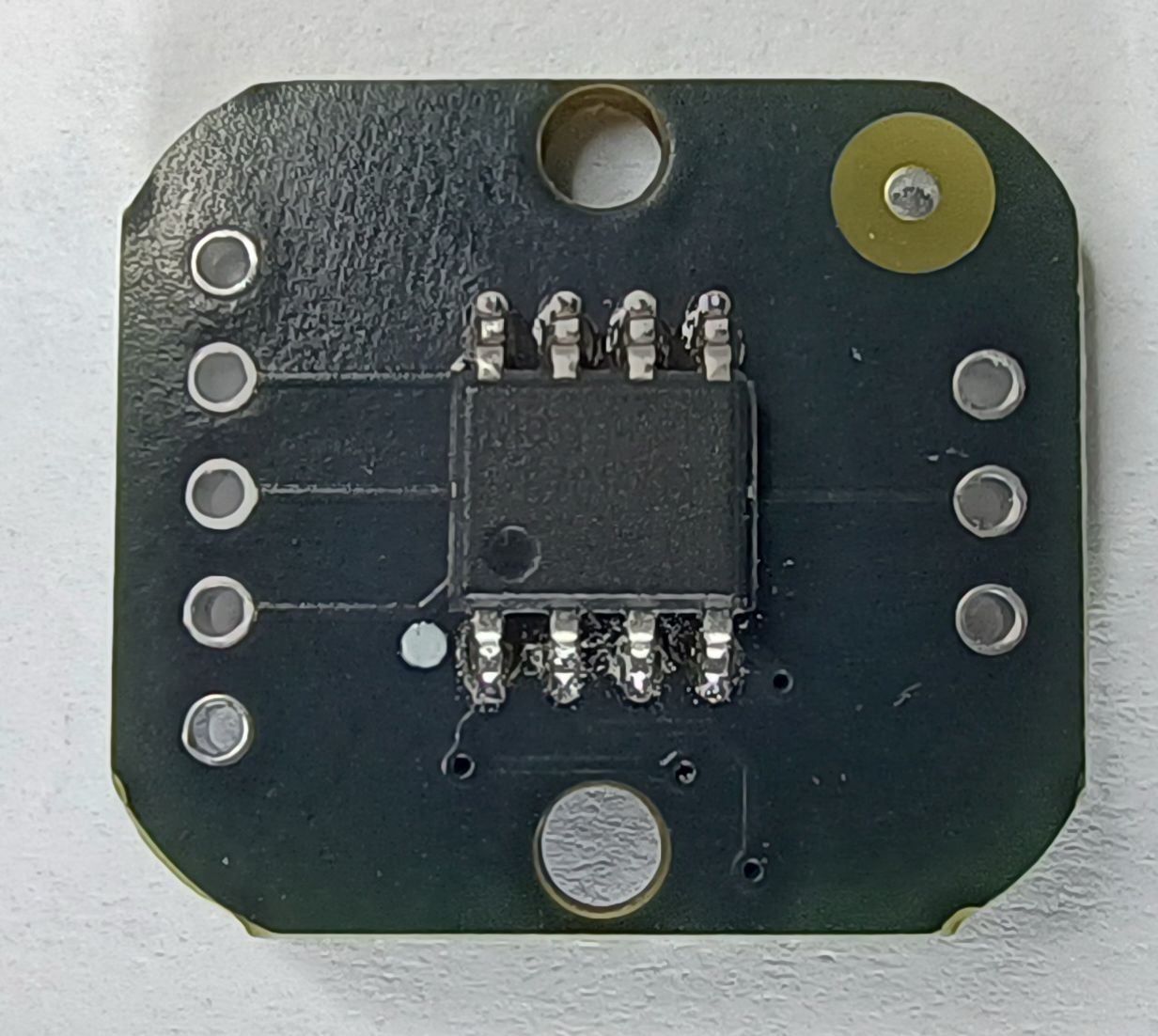
01355 module
The only marking on this module is 01355. There may be other similar modules with different markings. I purchased one of these modules here from AliExpress. It is currently selling for AU$2.72. Its size is 23mm x 23mm.
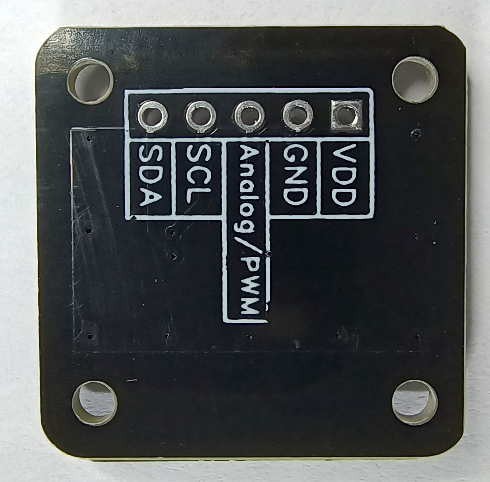
This module has 5 connections; VDD and GND. SCL and SCA which can be used for both I²C EEPROM programming and for the ABZ A and B outputs.
There is also an Analog/PWM connection. This comes from IC pin 3 and is not helpful for our use.
What is missing is the ability to set the mode. That is done with pin 2 on the IC. On this module the PCB connects pin 2 to VDD placing it in I²C mode. I’m not sure why it is connected to VDD as the IC has a built-in pullup resistor.

Programming the EEPROM
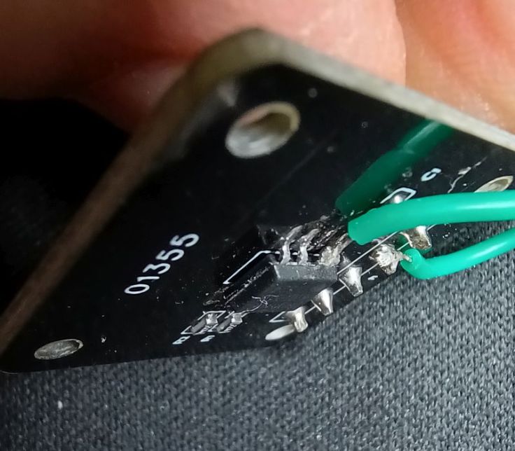
Programming the EEPROM can be done by making no changes to the module. However, to use it in ABZ (as a rotary encoder) mode I had to lift pin 2 off the PCB, solder a wire to the pin and connect it to GND.
I attempted to reprogram it, but this time I left pin 2 floating (relying on the built in pull up resistor) rather than connecting IC pin 2 to VCC and it was recognised as an I²C device and was able to program it again successfully.
This is the wire i attached to the lifted pin.
Pros
- Cheapest option
- Standard 2.54 mm headers
Cons
- Mode pin not accessible
- Requires hardware modification for ABZ use. This is doable, but it’s delicate and not something I’d recommend unless you’re comfortable modifying SMD parts.
- Easy to damage
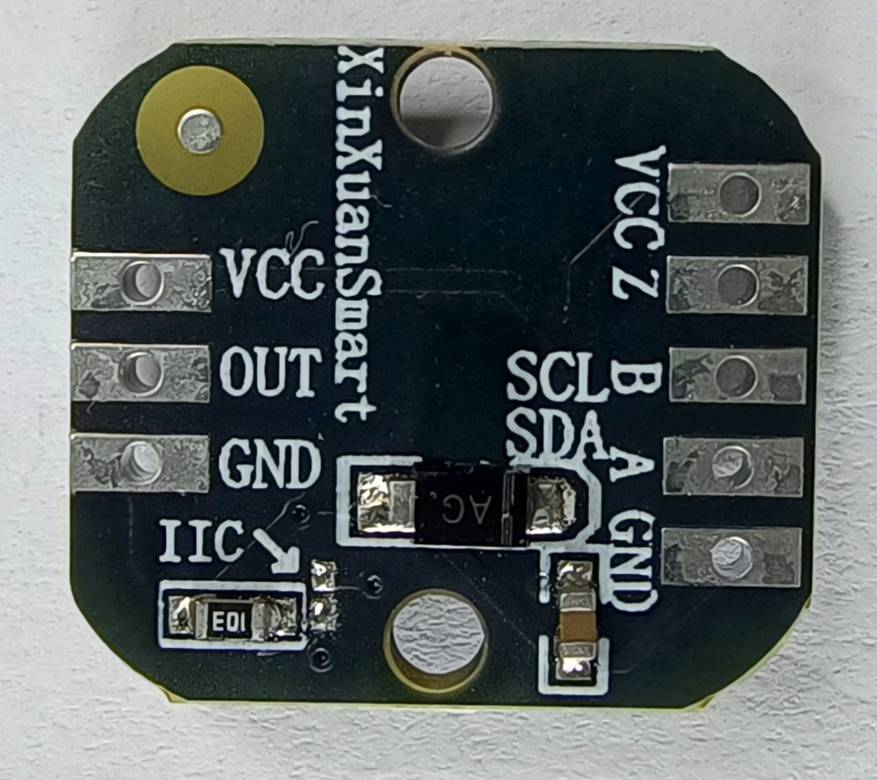
XunXuanSmart module
I purchased one of these modules from AliExpress here. It is currently selling for AU$4.29. It measures 15mm x 17mm
This module has pin header connections on one side for; VCC and GND, A / SDA and B / SCL, which can be used for ABZ mode and for I²C mode and EEPROM programming. There is also a pin for Z that I did not use.
On the other side there is a second VCC and GND and an OUT pin for analog or PWM output. This is something that I have not experimented with.
Programming the EEPROM
I was surprised when connecting this up that it wasn’t recognised as an I²C device. I found that this module was shipped already in ABZ mode and pre-programmed to 1024 resolution, whereas other modules come set to a 1 and come in I²C mode. Looking at listings for this module some list a feature as “ABZ mode with 1024 lines”.
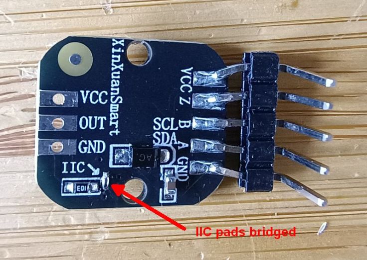
There are two pads on the PCB marked IIC. These set the mode to either ABZ mode (pads not connected) or I²C mode (pads shorted).
I bridged the IIC pads with solder and was able to reprogram the module to a different resolution. I removed the bridge after programming to place it back in ABZ mode and module worked as intended.
Pros
Smallest module. Has pads to set the mode.
- Compact
- Has pads to set the mode
Cons
- Most expensive
- 2 mm header spacing
- Mode pads are very small and fiddly to solder
Conclusion
It’s possible to program and use all these modules, but the first one is the easiest to use. While I was able to lift a leg of the IC on the 01355 module, it was challenging and I could have easily ended up damaging it.

Leave a comment