I have a great deal of trouble laying out items for project front panels, particularly where multiple holes have to be aligned. I don’t have a CNC router or other high tech tools. I just have old basic tools. I do have a basic saw bench but I think it is at least 70 years old. I also have a cheap small drill press.
Front Panel Designer
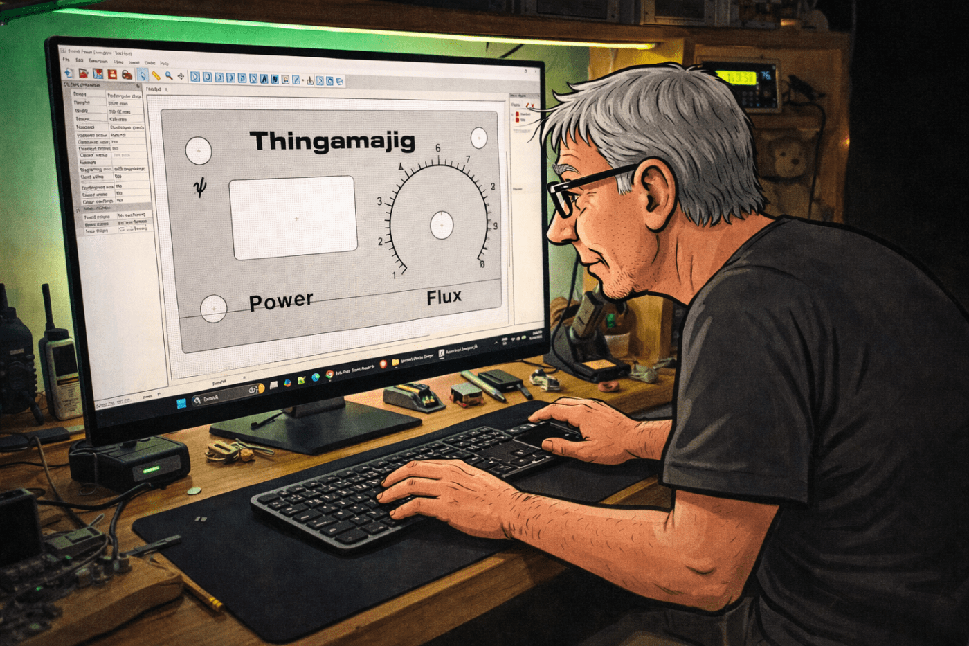
I started to look around for some free software to help out. I wanted something that was easy to learn and use. I came across Front Panel designer by Front Panel Express. This company specialises in making front panels and they provide the software free to allow customers to design panels for them to fabricate.
As the software is designed for producing panels, its tools are all designed for this task. When a panel has been designed it can be saved or printed to a printer or to PDF.
I gave the software a go and found it to be fairly easy to use. I downloaded it from their page and installation went smoothly. However, the version on the page is currently 6.5.0 and when I opened it it said there was a newer version (6.5.1) but I was not able to work out how to update to that, so I just ignored that message.
Using it
To start a new project a few things need to be set. The panel size needs the height and width. There are options for material and milling. I left those set at the default (Aluminum anodised). The colour shows on the working canvas, but when printing there is an option to print in wire mode which removes the panel colour.
There are a number of tools available in a toolbar. The ones I used were:

- Insert drill hole – inserts a round hole.
- Insert rectangular hole – inserts a square with an option to set the corner radius.
- Insert Text engraving object – adds text.
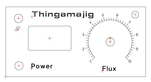
- Create scale – was used to add the 1 – 10 scale for the knob.
This is a test panel I did, to try out some of the features. Click on it to see a bigger image.
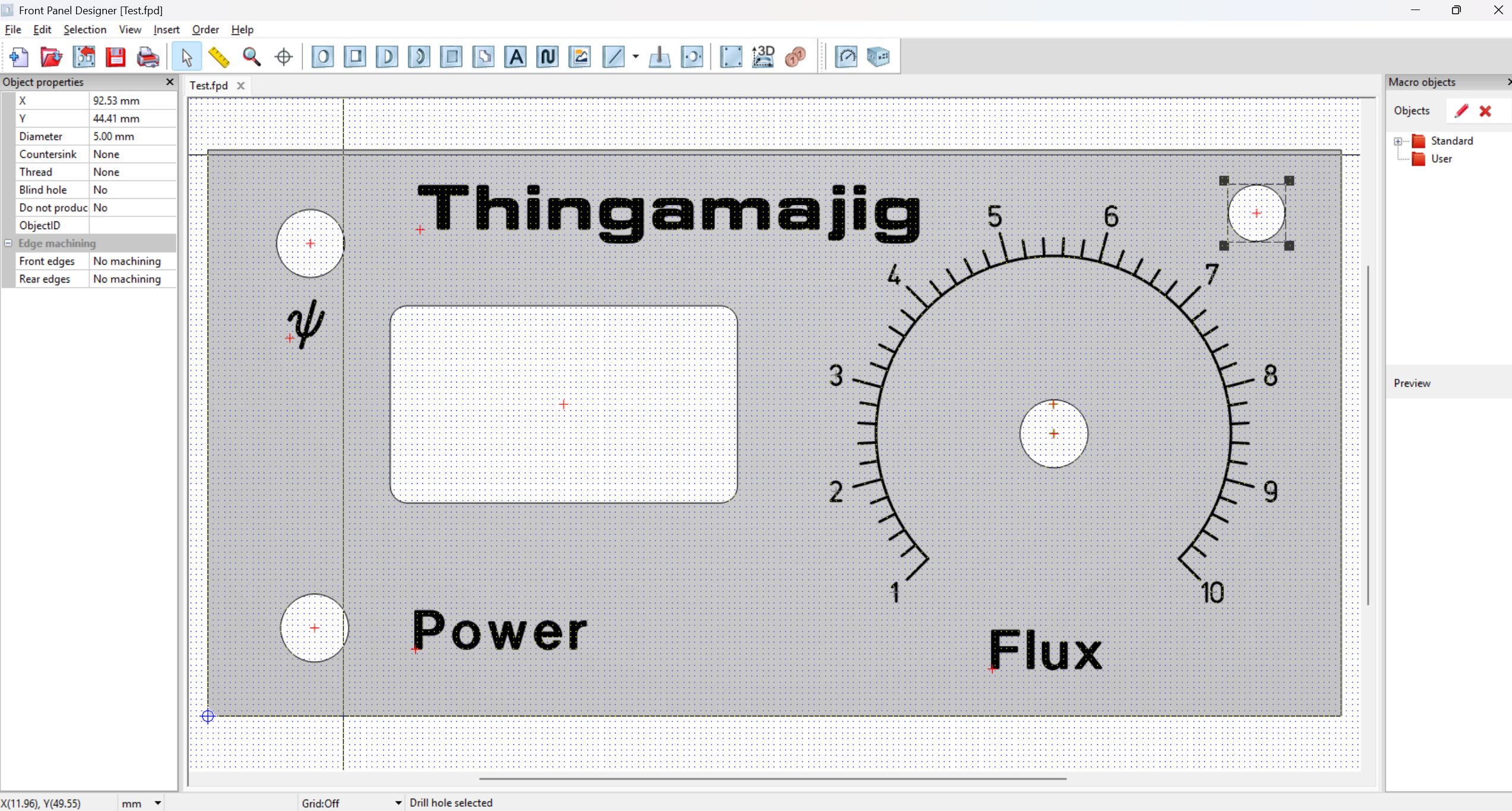
The side panel lists the selected object properties, including size and position. This makes precise placement straightforward. Multiple objects can be selected and aligned vertically or horizontally or all moved together.
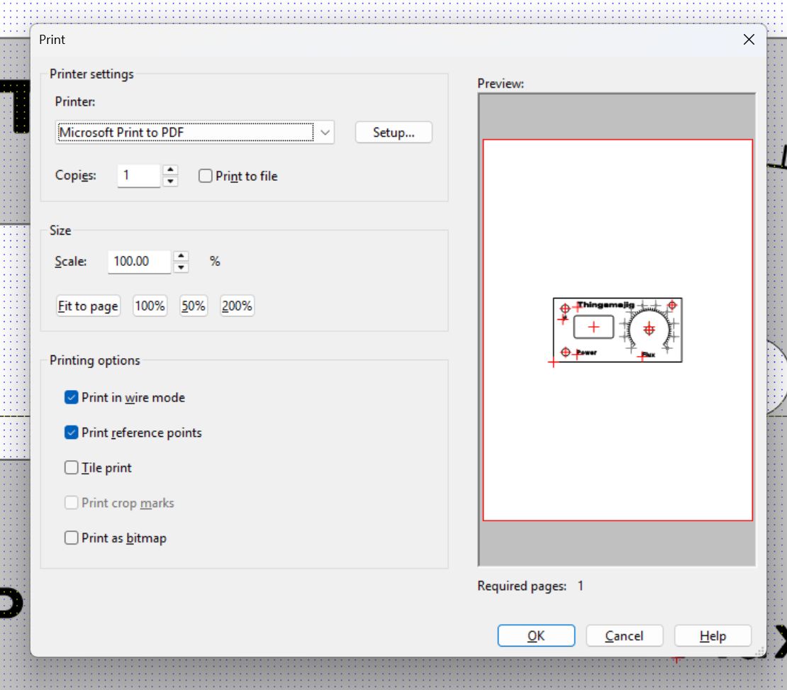
The print menu has a few useful options. You will likely need to set the scale to 100%, but you will also need to check the printed copy to make sure the scaling gives correct measurements on the printed copy.
Print in wire mode hides the panel colour. Print reference points toggles the alignment marks on and off.
This is what displayed on the print version with the reference points off.
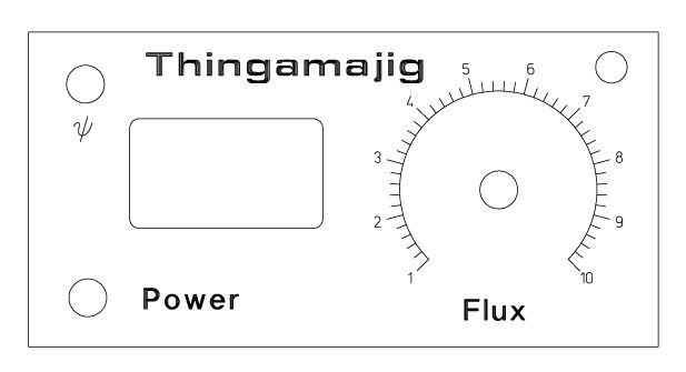
This is with them on. The marks are useful when drilling holes.
Final thoughts and questions?
I had thought of gluing the printed paper version to timber or aluminium and them putting a layer of protection over it. I haven’t tried that yet. I’ve only used it to make the layout and drill marks for a couple of projects and that worked very well. One of the projects was the SI4732 AM, LW, SW, FM Receiver. I can’t see how to have fancy colours so that’s a potential limit if using the actual print paper for a front panel.
I haven’t tried other software so I don’t have anything to compare it with. Have you tried this software? Do you have any other recommendations?

Leave a comment