
I’ve been working on a SI4732 radio for nearly two months and it’s finally finished. The SI4732-A10 is a cheap little IC that contains almost everything needed for an LW, AM, FM, and SW radio. It is controlled through an I²C interface. There are lots of radios out there based on this design, including the popular ATS-20+. There are also a lot of home built ones that use the excellent PU2CLR SI4735 Library for Arduino. The SI4735 is related to the SI4732 and the library supports both.
I wanted to use that library to make a radio with:
- Ergonomics first.
- Big enough to be comfortable.
- No menus. No touchscreens.
- Every function on a button or knob.
- A colour LCD.
- A proper speaker.
- Something better than a cheap rotary encoder.
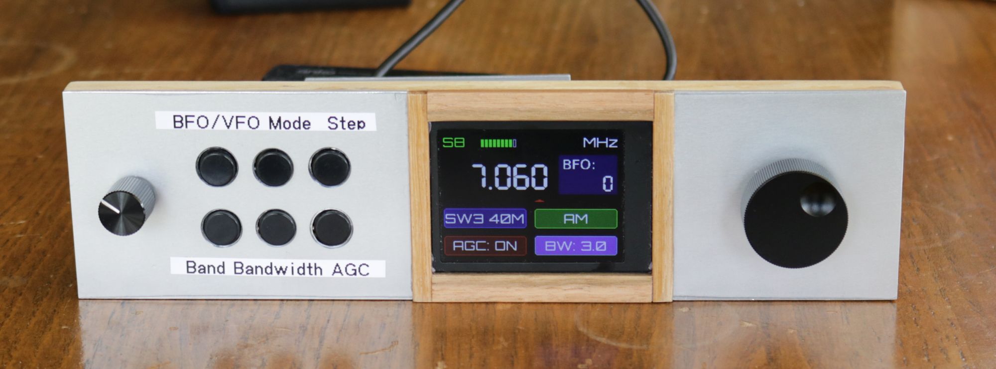
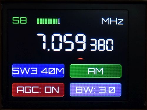
Here are a few images of the final build. This is the front without its outer case.
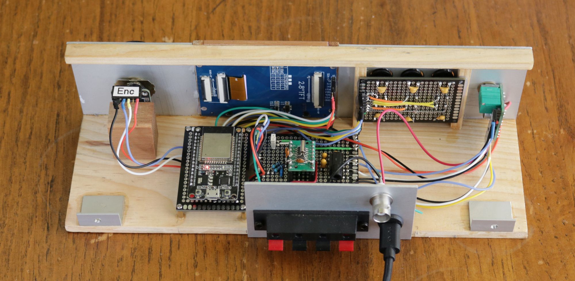
This is a look inside. Notice the space for future mods, but no built-in speaker or battery.
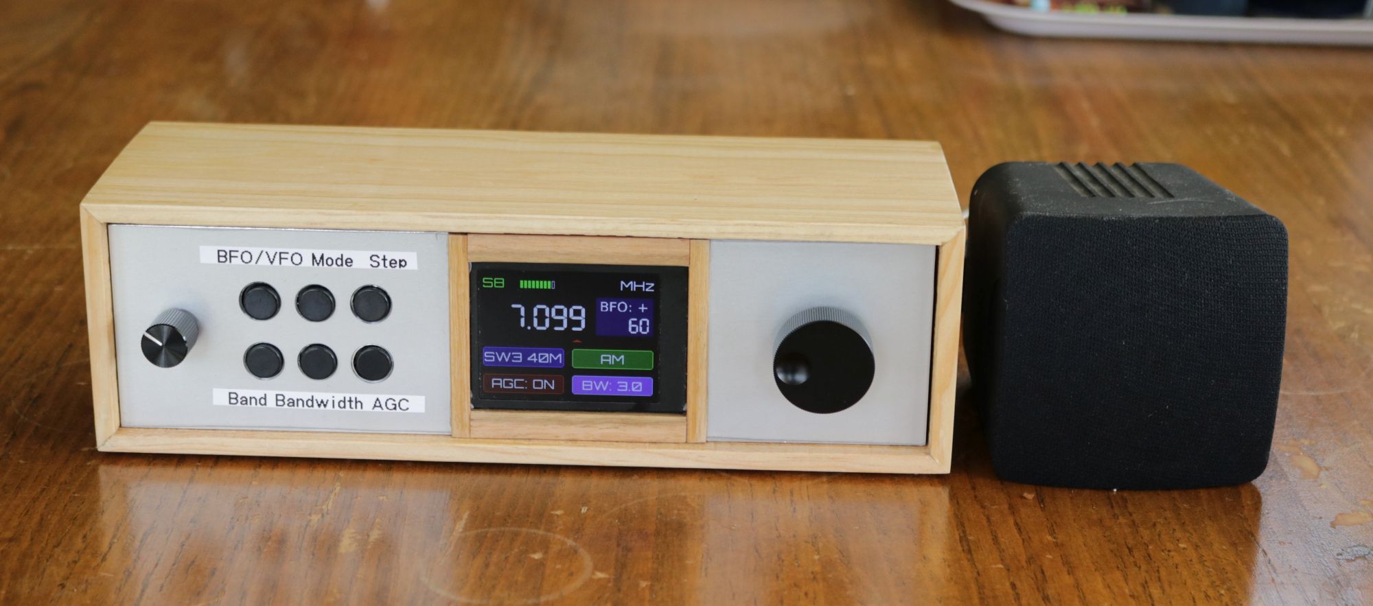
The front with case fitted and an external speaker.
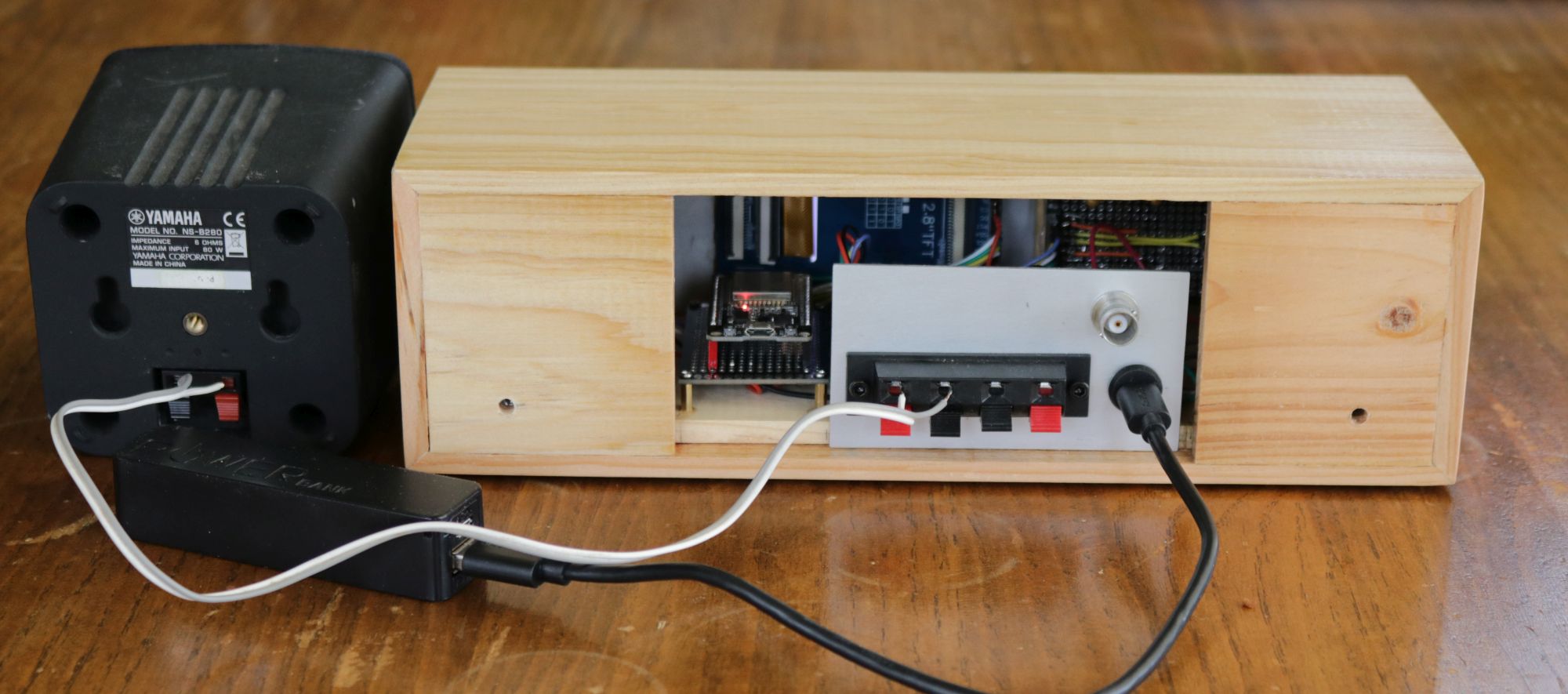
A shot from the back.
Software
Choosing an example to start with
I looked at the examples in the PU2CLR library and found SI47XX_09_NOKIA_5110. This had buttons for the controls I wanted, but was designed for a Arduino ATmega328 Pro Mini microcontroller and a Nokia 5110 monochrome display. I thought it may be easiest to start with that and change the display and mcu.
Changing the MCU and LCD
I got it working and then worked with Claude to change the software over to work with the colour display and ESP32. Claude got it working, but the display was a bit ordinary. The fonts were ugly. It flickered when changing settings. Also, the text on the display got smaller towards the bottom, presumably as Claude tried to make everything fit. But to be fair, it worked.
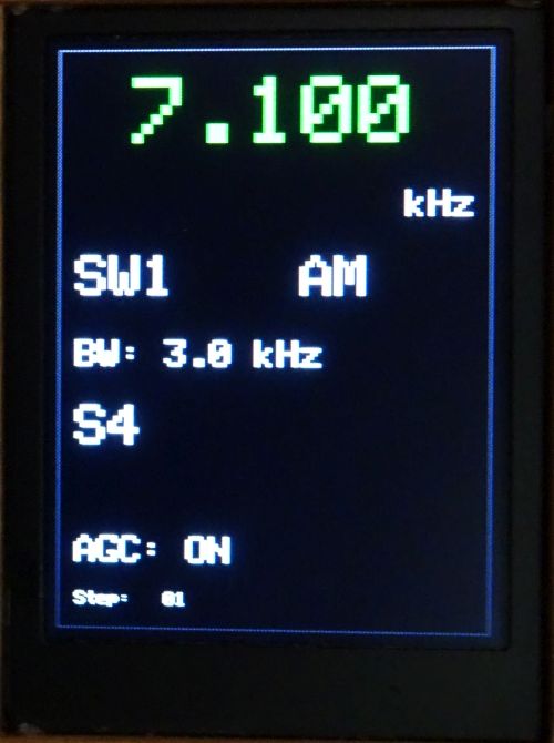
While Claude helped me understand coding for the display, I did most of the work for that. While I originally thought these displays could be a good replacement for the simple 16X2 LCD displays I have often used, it’s not that simple. The cost is comparable, but these displays do take considerably more work to get a nice result. I did use sprites for display of content as this ensured the display contents don’t flicker when changing the frequency or other settings.
Experimenting with the BFO
When I discovered that the SI4732 didn’t support sub kHz tuning I started thinking about options. I had a lot of trouble locating information about how the BFO works with these ICs. I turned to AI and it said, “When in SSB mode, the BFO control allows users to shift the frequency up or down (e.g., by a few kHz) to zero-beat the signal and achieve clear audio, a key feature in DIY receivers.”
I took this to mean that it acted like fine tuning and asked Claude to make the frequency display in Hz and when selecting the step size enable the BFO for sub kHz steps. If the user adjusted the BFO steps and it passed ±1000 Hz, it would automatically adjust the VFO and reset BFO to the opposite side to continue smooth tuning.
It looked good and appeared to work well. Sadly, while I don’t believe the BFO works the same way as in old analogue radios, I don’t think this way is having the intended effect. It sounded like fine tuning. I’m no longer convinced it actually adjusting the frequency as I had thought. Reluctantly, this code was removed.
Code review
I asked Claude to do a complete code review. It recommended a lot of changes and I went ahead with them. The result was a significantly changed sketch with many parts removed and placed in separate files. I was surprised by how well this went and how few errors needed to be fixed as a result.
Hardware
ESP32
The software example I started with used an Arduino Pro Mini, but I wanted to use an ESP32. All the hardware I was using would run off 3.3V, although I’m running the amp from 5V. The ESP32 is fast and has enough pins for this project.
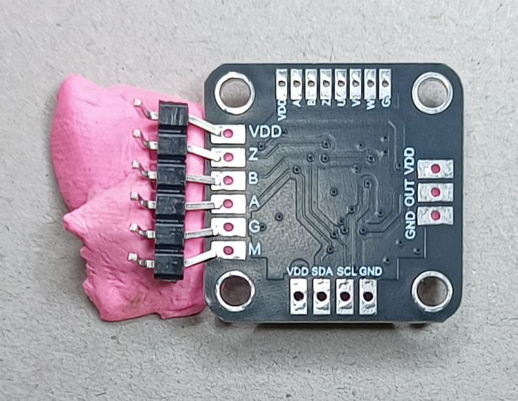
Magnetic rotary encoder
The original plan used a regular mechanical rotary encoder. I tested the software with one and it works with it. However, for my final build I’ve used a MT6701 magnetic angle senor that has a quadrature output. I dismantled an old potentiometer and glued a magnet to its shaft. This worked well, but it has the downside if not having a built in button like the mechanical rotary encoders do.
If you are interested in this have a look at my post Replacing a Rotary Encoder with a Magnetic Sensor and Potentiometer. I’ve updated the software used to set the PPM so it is easy to use.
I soldered a header pin onto the module so I could easily reprogram the PPM if I wanted to. It’s not 2.54 mm pitch so some bodging was required. Notice, I’ve moved up to coloured BlueTack.
Displays
I don’t like the Nokia 5110 displays and wanted to go colour. LCD displays are now cheap. I tested two that I have. The first was a 2″ 240 x 320 display like this one. The sales page lists it as an OLED LCD. From what I can tell it is an LCD screen not OLED. AI says it is a TFT LCD display. It is a very nice looking display, but it is very bright and it doesn’t have a connection for backlight. I couldn’t find a way to dim the display using the library. Claude suggested a function that set the colours to be a darker shade.
I also had a 2.8″ 240 x 320 display like the one here. This is the same resolution, but is larger, has a matte (less reflective) screen and a separate backlight. I preferred this so went with it.
This is what they look like from the back, so you can see the pins and other info.
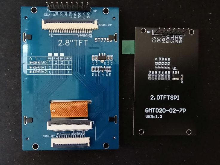
Both displays use the same ST7789 driver code and use SPI. Swapping only requires the modification of one line in the LGFX_ST7789.h file:
cfg.invert = false;  // 2.8 display
cfg.invert = true;  // 2.0 display
Amplifier
I chose the amplifier module based on what I had and how easy it would be to use. It’s a PAM8403 based stereo module, like this one. I’ve had this module for a long time. It can be powered from 2.5V to 5.5V. It looked ideal and has a built-in volume control. It looked like I would be able to mount the whole thing just by using the potentiometer nut. The potentiometer also has a power switch that I thought I may be able to tap into to control the power for the whole radio.
I’m very happy with the audio quality of the module. It was just as easy to mount it as I had hoped. I was able to use its power switch to control power to the whole radio. I connected it to the leg of the switch on the back of the PCB. That leg is surrounded by a ground trace which made soldering a bit tricky and risks shorting the power supply if not done correctly. I later found I could probably have connected it to one of the capacitors on the top side of the PCB. That would probably have been better.
This appears to be the power after the switch that I could have used.
There is another important thing to note about this amplifier. The outputs do not share a separate ground. the outputs are:
- Right output –
- Right output +
- Left output +
- Left output –
What this means is that a 3.5 mm headphone socket can’t be used for stereo, because that requires a shared ground. That’s not much of a problem for me as I don’t intend to use a headphone, nor FM which is the only stereo output from the SI4732. I could have just connected to 3.5mm one channel of the amp, but I had some speaker terminals so used those.
Construction
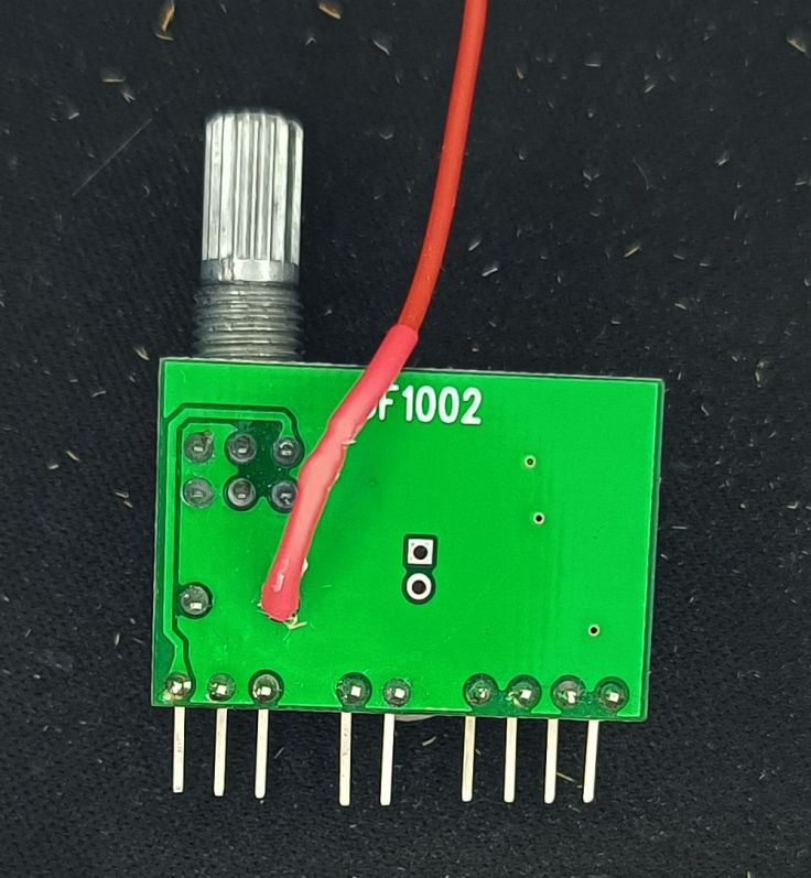
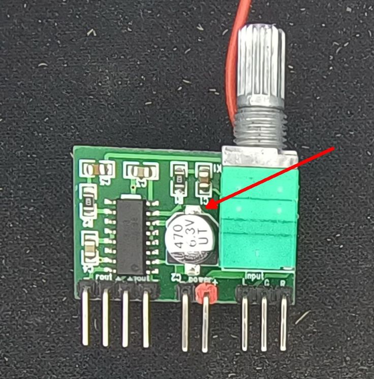
The SI4732 IC and supporting components
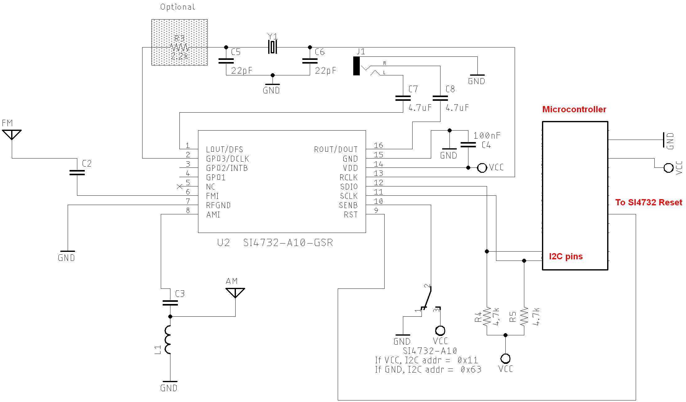
I started with a breadboard, but quickly decided to go to a more modular construction. I looked at the SI4732 circuit diagrams and decided to create a module with it and its support components. The Preface library page has information about the circuit. The SI4732 part of the circuit I am using is very similar to the one on the library circuits page under All Sketches on SI47XX_01_SERIAL_MONITOR folder. It’s the one for the SI4732-A10 Version. I didn’t include the AM coil and I am using an ESP32, not an Arduino Pro Mini. This is a modified copy of the image from there. This shows the diagram of just the radio part and how it connects to the microcontroller. Click on it to see a bigger version
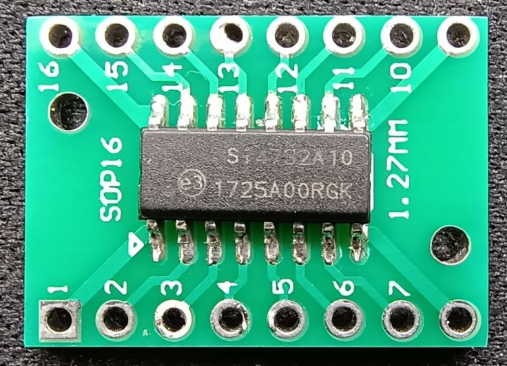
I started with a 16 pin IC breakout board and mounted the SI4732 IC.
I added the crystal and 2 x 22pF capacitors. For a while I used it like this, but it is very messy and I was thinking I could make a more complete module.
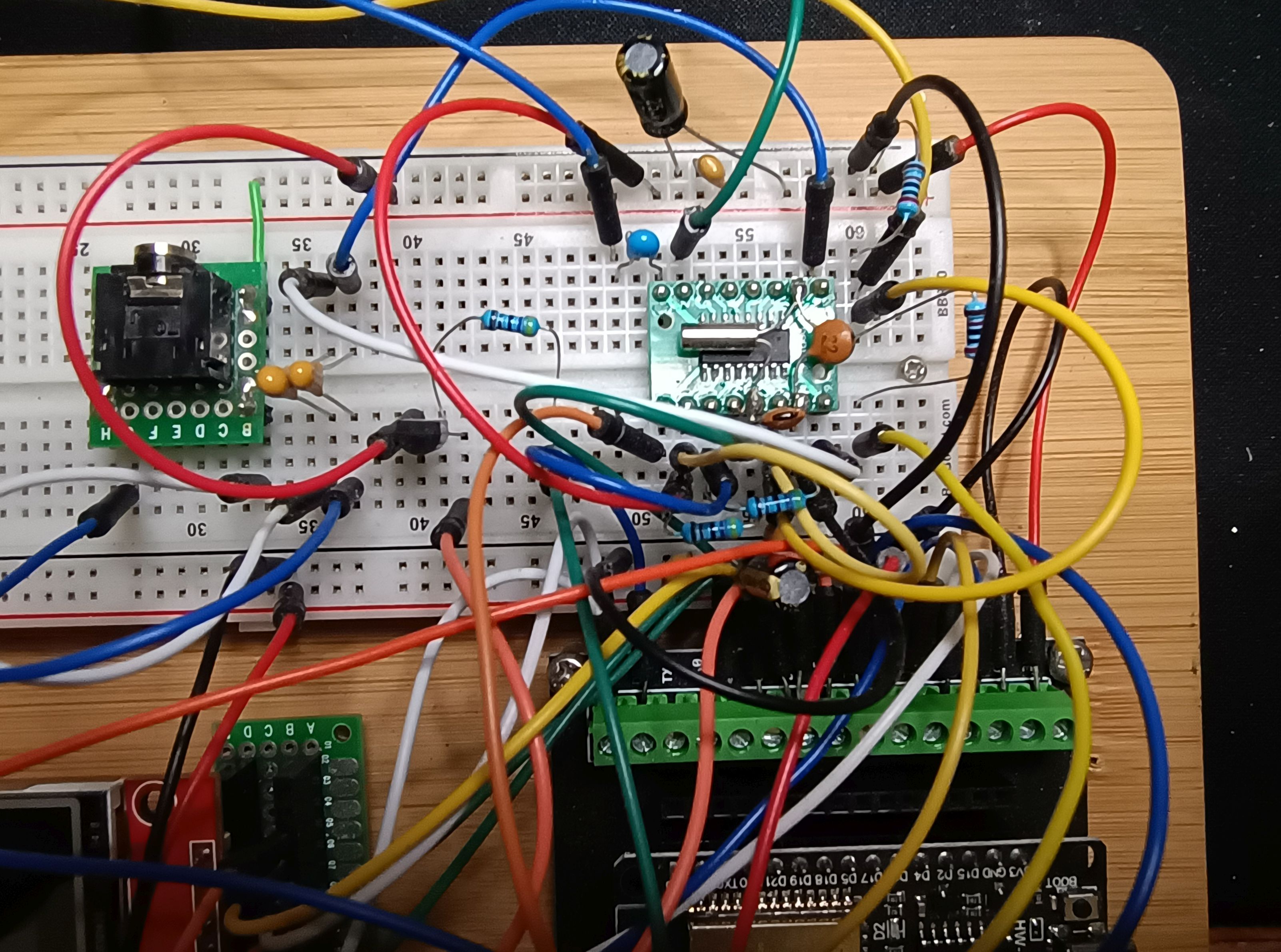
I mounted this board onto a bigger PCB and mounted the rest of the IC support components on it. I think the online sellers are missing an opportunity by not selling a module for the SI4732.
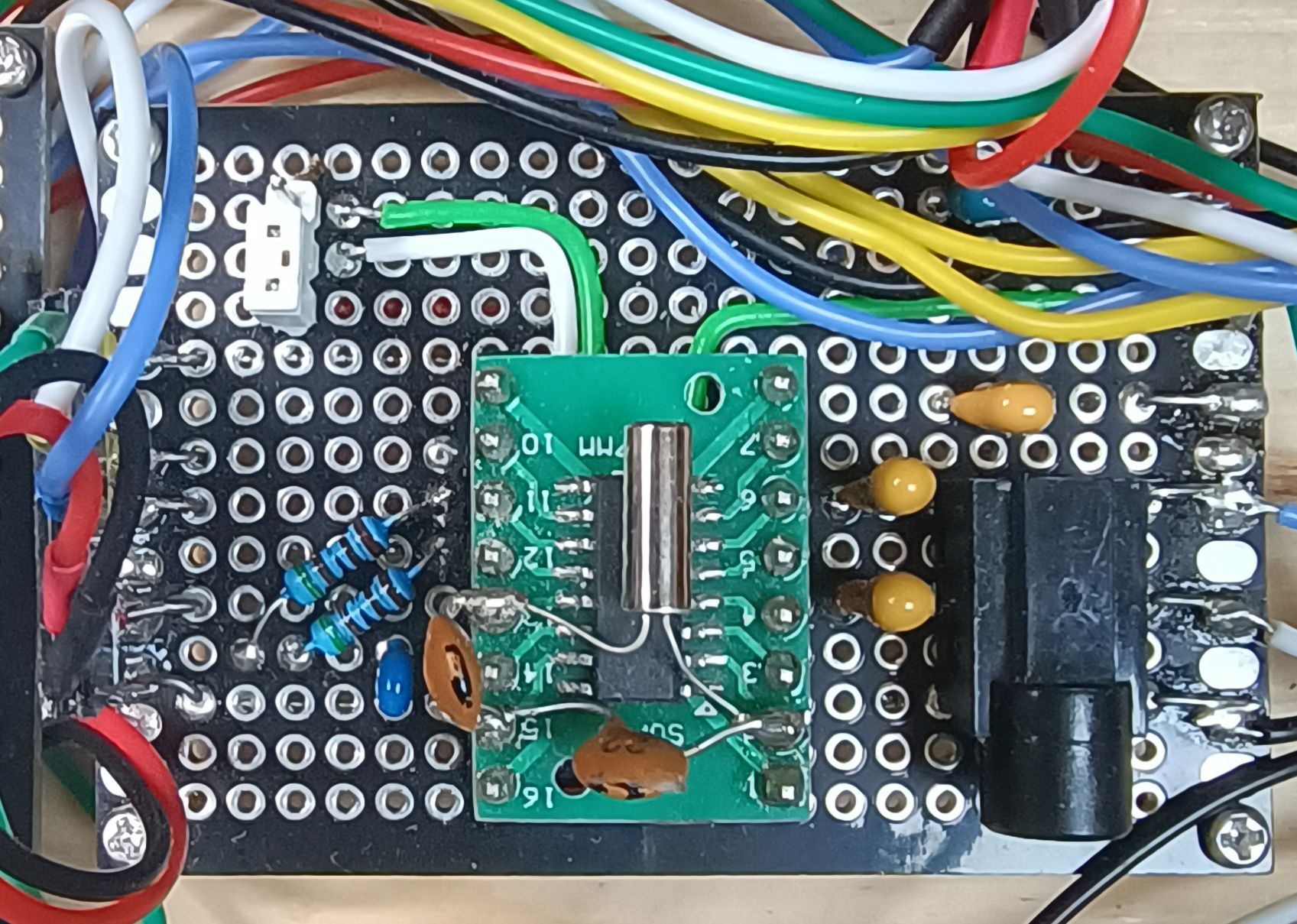
If I did it again I would try and add even more of the components onto the IC board, including the 2 x 4.7K pullup resistors.
Buttons
I had successfully made a button board before using a prototype board. I did this again as it is easy and ensures all the buttons are equally spaced.
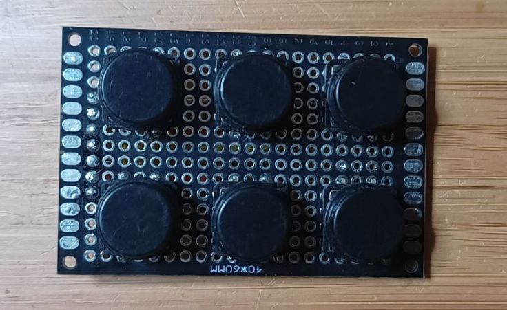
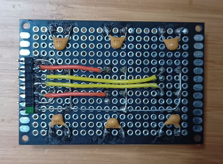
All buttons are connected between an ESP32 pin and ground. Internal pullup resistors in the ESP are enabled. I added 1nF capacitors across the contacts for debouncing, but I don’t think that is necessary with the software I am using.
Connecting the bits together
I haven’t draw a complete circuit diagram, but I have included the wiring connections to all the parts parts in GitHub. I originally was quite confused by these radio circuit diagrams, but when I looked closely, they nearly all have the same circuitry for the radio IC and the rest are just buttons, displays, an encoder connected to a microcontroller in standard ways.
Enclosure
I went with a timber enclosure, but this time I tried a couple of different things. I used a piece of scrap aluminium panel for the front panel and part of the back. I balked at trying to cut a square hole for the display and instead made the front from 2 pieces of aluminium and made a bezel out of timber. The aluminium and timber were all joined using super glue. This worked quite well and I’ll do that again.
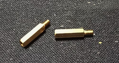
The prototype boards are mounted on 2mm brass standoffs. I drilled small holes for the male end and then put super glue in the holes and tapped them in with a hammer. A bit of a bodge, but worked well.
The rest of the enclosure was made from 60 year old scraps of pine that had been destined as sides for timber crates.
Cost
This was the cost of the main parts. Some things have gone up in price, others are now cheaper.
- 1 x ESP32 Dev Module AU$3.00
- 1 x SI4732 IC AU$4.36
- 1 x 32.768 kHz crystal AU$3.59 for a box of crystals
- 1 x MT6701 magnetic encoder module (or use standard encoder) AU$3.65
- 1 x PAM8403 Amplifier module AU$2.75
- 1 x 320×480 SPI TFT Display AU$9.63
There were quite a few other parts that I already had and don’t have a price.
- Volume and tuning knobs
- 6 x button switches
- 2 x 22pf capacitors
- 2 x 4.7uF capacitors
- 1 x 100nF capacitor
- 6 x 100nF capacitors (for buttons, may not be needed)
- 2 x 4.7K resistors (pullups)
- Hookup wire
- 16 pin IC breakout board
- Standoffs
- Speaker
- power, speaker and antenna sockets
- Potentiometer for encoder shaft
- Case
All up it probably cost around AU$30.00
Final thoughts
So here it is in action, well at least it’s how ChatGPT envisioned it in action. That’s not supposed to be me, and my work area is not that interesting.

I think this is a fun project. I’m happy with the reception I’m getting, but I don’t think I would do it quite the same again. I thought this would be more like a communications receiver that I would spend time tuning around, but I don’t see it as being really good for that due to the chuffing.
Chuffing
I wasn’t aware that there would be the chuffing sound when changing frequency, but this seems to be a by product of this type of IC. I find this annoying enough that I find I’m not tuning over large parts for the frequency, rather I’m using it to listen to small portions of bands. I was expecting it to be like tuning on an old analogue radio. For me this makes it more suitable as a radio that you don’t adjust much and so the large size and number of buttons are not so important for that. If I make another, and I’m considering it, I will aim for a compact design.
Frequency steps
I assumed it would support 1Hz frequency steps, whereas it is 1kHz steps. My attempt to get around that by integrating the BFO oscillator didn’t work. Maybe I’m asking for too much. It’s a lesson in not making assumptions.
Rotary encoder
The encoder I made from the MT6701 works really well for adjusting the tuning. It wasn’t as good adjusting the other settings, particularly selecting the band. The physical detents in a regular encoder would be better for that.
Size and case
I like the aluminium panel and I found it good to work with. The step drill I used made it easy to make clean holes. Gluing the aluminium to timber with super glue also worked well. However, I prefer the radio out of it’s box and when I do another project of this size I’ll consider making it on a thicker baseboard and not having it in a box.
More info
Here are some useful links:
- My GitHub repo with the more info and the code
- The SI4735 datasheet
- The SI4732 datasheet
- The AN332: Si47xx Programming Guide
- The PU2CLR arduino library
- The PU2CLR example this receiver is based on
Would I do it again?
Yes, but I would not make it so big. It does receive quite well. While it’s not the same as building an analogue radio, I think these radios are a fun project for someone that enjoys microcontrollers and would like to build a simple radio.

That casing and front facia remind me of Leak Audio integrateds.
LikeLike
I hadn’t heard of those before, but I can see the similarity. Looks like they are high end gear, which may be why I hadn’t hear of they. I guess they didn’t use old bits of aluminium from the end of an old awning for there panels 🙂
LikeLiked by 1 person
😂
LikeLike