The first thing most of us do when learning Arduino try a blink sketch. In my quest to learn how to use cheap LCDs, I thought I’d do the same. In this case a simple animation blinking an eye. The plan was to make it display a couple of images; a closeup of an eye open and then quickly display a closed eye and then back to the open eye.
I thought I had seen plans for this before, but when I went searching I couldn’t find any, at least not just simple blinking, so decided to start from scratch with the help of AI.
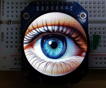
The hardware I used was an ESP32 Dev Module and a cheap 240×240 pixel round LCD display based on the SGC9A01 controller, like this one. It could be done with other displays, but the LCD config code would need to be changed. I did a post LovyanGFX Display Config Code: ILI9341, GC9A01 and ST7789 Displays showing how I got the config code.
I’ve made a couple of sketches. One just displays a single eye that blinks every 3 seconds and then displays a closed eye for 100 ms and then loops. The other is open for a random time between 1 and 5 seconds and then closes for 100 to 500 ms. It should be fairly easy to modify these to use your own images and do a more complex animation.
Obtaining the images
To start, I needed some images. I decided to give ChatGPT’s image generator a go. After a lot of fiddling around, I had some success.
My main requirement was that it could make multiple images of the same eye. ChatGPT can manage that, although it isn’t perfect. It helped me refine the prompts, like these:
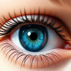
Neutral gaze: A hyper-realistic close-up of a human eye with a vivid blue iris, open and looking straight ahead. Fine lashes, detailed skin texture, and soft reflection lighting. Neutral gaze, natural eye moisture and subtle shadows.
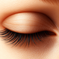
Fully closed: The same eye now fully closed. Lashes rest naturally, eyelid relaxed with smooth shading. Lighting and composition identical to previous frames for continuity.
Glancing left: The same blue eye reopened and glancing naturally to the left. Upper eyelid slightly lowers, lower lid subtly raises. Iris shifts left with gentle perspective distortion. Same lighting and framing.
It mostly worked, but I ran into three issues:
- I told it to make them 240×240 pixels. It said it would, but it kept making them at 1024×1024. This wasn’t a big deal, but I think the bigger images used up my daily allowance much faster.
- It’s not good with left and right. It got the “glancing to the left” correct, but the “glancing to the right” was also glancing to the left.
- That daily limit with the free account ends quickly when generating images. It took a few days to create enough image as few that weren’t quite right.
If your try this, it may help to start the prompt by telling it that you are creating these images for an animation. Halfway through creating them ChatGPT sort of figured out that was what I was trying to do.
Formatting the images
I wanted the images to be the same size as my display. That meant sizing them to 240 x 240. I suspect most image viewers can handle this. I use Irfanview. It’s more of a viewer than an editor, but has enough tools for me, and makes it easy to crop and resize images.
These are the images I finished with. They are 240 x 240 pixels.
Converting the images into numbers
There are a couple of ways to display the images. One is to upload the images to a SD card and connect a it the EPS32. Images can then be loaded from the card. I haven’t tried that.
Another way is to convert the images into a data array and add this to your Arduino program. As I was only going to use a few images and wanted to keep it simple I went for this method.
I found a an online converter, but I was overwhelmed by ads. The LovyanGFX library apparently has one built in, though I couldn’t make much sense of it.
So, I turned to Claude. It offered a Python script. I haven’t used Python and with some prompting, it kindly made a standalone web tool instead. There’s more about that adventure in my post I Asked Claude for Info, and It Built a Standalone Tool. I’ve included it in the GitHub with all the files for these animation sketches, or if you prefer you can use it directly at this Github page. I’ll add info below about getting all of them if you want to give it a go.
The converter converts regular image files (PNG, JPG, etc.) into C/C++ arrays that Arduino can understand and store in its memory. The process it does is:
- Reads an image (any format: PNG, JPG, GIF, etc.)
- Extracts pixel data – gets the colour of every single pixel
- Converts colours from RGB888 (24-bit) to RGB565 (16-bit)
- Generates C code – creates a proper C array with hex values
- Outputs a .h header file ready to include in Arduino
Displaying the images
Once I had the image data, displaying images was reasonably easy. I started with the Arduino IDE with the LovyanGFX library installed. I installed it from the Library manager in the IDE. It’s the one by lovyan03.
I created a new sketch. I left the main file tab empty at this stage.
LCD config data
I added another tab, by selecting the three dots at the top right and selecting New Tab. This tab was for the LCD configuration data. As it is based on a SGC9A01 driver I called it LGFX_SGC9A01_240x240.h.
I added the driver code to that tab. This is the code I added. It’s also in my post LovyanGFX Display Config Code: ILI9341, GC9A01 and ST7789 Displays.
/* GC9A01 configuration for ESP32 (240x240 circular display)

  SPI Wiring:
    Display SCL → ESP32 GPIO 18
    Display SDA → ESP32 GPIO 23
    Display CS → ESP32 GPIO 15
    Display DC (or RS) → ESP32 GPIO 5
    Display RES (or RESET) → ESP32 GPIO 4
    Display VCC → 3.3V or 5V
    Display GND → GND
    Display BLK → Not connected.
*/

class LGFX : public lgfx::LGFX_Device
{
  lgfx::Panel_GC9A01 _panel_instance;
  lgfx::Bus_SPI _bus_instance;

public:
  LGFX(void)
  {
    {
      auto cfg = _bus_instance.config();
      cfg.spi_host = VSPI_HOST;     // ESP32 VSPI (SPI3)
      cfg.spi_mode = 0;
      cfg.freq_write = 40000000;    // 40MHz (GC9A01 supports high speeds)
      cfg.freq_read  = 16000000;
      cfg.spi_3wire  = true;
      cfg.use_lock   = true;
      cfg.dma_channel = SPI_DMA_CH_AUTO;
      cfg.pin_sclk = 18;            // SPI SCK (connect to display SCL)
      cfg.pin_mosi = 23;            // SPI MOSI (connect to display SDA)
      cfg.pin_miso = 19;            // SPI MISO (not connected)
      cfg.pin_dc   = 5;             // Data/Command pin
      _bus_instance.config(cfg);
      _panel_instance.setBus(&_bus_instance);
    }

    {
      auto cfg = _panel_instance.config();
      cfg.pin_cs           = 15;    // Chip Select
      cfg.pin_rst          = 4;     // Reset
      cfg.pin_busy         = -1;    // Not used
      cfg.panel_width      = 240;   // Physical width (circular display)
      cfg.panel_height     = 240;   // Physical height (circular display)
      cfg.offset_x         = 0;     // X offset
      cfg.offset_y         = 0;     // Y offset
      cfg.offset_rotation  = 0;
      cfg.dummy_read_pixel = 8;
      cfg.dummy_read_bits  = 1;
      cfg.readable         = false;
      cfg.invert           = true;  // Color inversion (toggle if colors look wrong)
      cfg.rgb_order        = false; // RGB order for GC9A01
      cfg.dlen_16bit       = false;
      cfg.bus_shared       = true;

      _panel_instance.config(cfg);
    }

    setPanel(&_panel_instance);
  }
};
Image data
I created another tab, again selecting the three dots at the top right and selecting New Tab. This one is for the first image data. I called it eye_open_center.h and pasted in the code from the image converter.
This code is very long, so I’ll just list part of it here.
// Image: eye_01_open_center_256
// Size: 240x240
// Array size: 112.5 KB

#ifndef EYE_01_OPEN_CENTER_256_H
#define EYE_01_OPEN_CENTER_256_H

const int EYE_01_OPEN_CENTER_256_WIDTH = 240;
const int EYE_01_OPEN_CENTER_256_HEIGHT = 240;

const uint16_t eye_open_center_data[57600] PROGMEM = {
  0x7A44, 0x8203, 0x7A44, 0x69A2, 0x69A2, 0x7203, 0x7203, 0x5941, 0x7204, 0x7A02, 0x69A2, 0x61A2,
  0x7203, 0x69A2, 0x5121, 0x5121, 0x5121, 0x5941, 0x4901, 0x4942, 0x5962, 0x69A2, 0x69A2, 0x5941,
.
.
.
.
  0x9284, 0x8A85, 0x8A85, 0x8A84, 0x8A84, 0x8A84, 0x8A84, 0x8244, 0x8244, 0x8244, 0x8265, 0x8244
};

#endif
I created another tab for the second image. This one I called eye_closed.h and pasted in the code from the image converter for that image, the same way I did for the image above.
Main code
I added the main code below. Notice there are some includes at the top. One is for the graphics library and the other three are for the three other files/tabs that were created above. These names need to match the tabs.
The images are displayed in the loop and the lines to do this use eye_open_center_data and eye_closed_data. These are the names of the arrays that were defined in the image tabs. The names need to match.
#include <LovyanGFX.hpp>
#include "LGFX_SGC9A01_240x240.h"
#include "eye_open_center.h"
#include "eye_closed.h"

const int IMAGE_WIDTH = 240;
const int IMAGE_HEIGHT = 240;

static LGFX lcd;

void setup() {
  lcd.init();
  lcd.setRotation(0);
  //lcd.setColorDepth(16); // 16-bit RGB565 (default, 65,536 colors)
  lcd.setSwapBytes(true);
  lcd.fillScreen(TFT_BLACK);
}

void loop() {
  lcd.pushImage(0, 0, IMAGE_WIDTH, IMAGE_HEIGHT, eye_open_center_data);
  delay(3000);

  lcd.pushImage(0, 0, IMAGE_WIDTH, IMAGE_HEIGHT, eye_closed_data);
  delay(100);
}
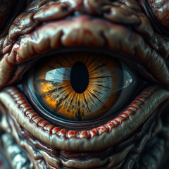
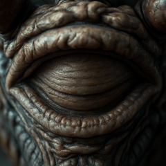
The second sketch for the monster eye was made using a similar method.
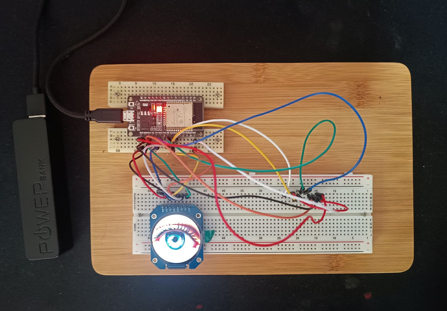
Wiring it up
Wiring was fairly straightforward as there is only the ESP32 and the display. It only gets challenging if the display uses different names for the connections. These are what I used. The connections are set in the LGFX_SGC9A01_240x240.h file/tab.
Display SCL → ESP32 GPIO 18Display SDA → ESP32 GPIO 23Display CS → ESP32 GPIO 15Display DC (or RS) → ESP32 GPIO 5Display RES (or RESET) → ESP32 GPIO 4Display VCC → 3.3V or 5VDisplay GND → GNDDisplay BLK → Not connected.
This is my setup. There are second set of wires. Ignore those, they were used to experiment with a different display. I know, the image is next to useless. The list above is more useful.
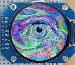
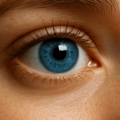
A couple of things to watch for
Initially the images displayed, but the colours were all wrong. An eye image looked like the one on the left, whereas it should have looked like the one on the right.
I tracked this down to this line which I had not included:
lcd.setSwapBytes(true);
Apparently the bytes need to be swapped for this display. Including this line fixed the issue.
The library also has a setColorDepth command. For these images it would be:
lcd.setColorDepth(16);
It’s not included in these sketches as the default is 16, which is what I’m using. There are some other options you could try. The options are:
lcd.setColorDepth(1);   // 1-bit (monochrome)
lcd.setColorDepth(8);   // 8-bit (256 color palette)
lcd.setColorDepth(16);  // 16-bit RGB565 (default, 65,536 colors)
lcd.setColorDepth(24);  // 24-bit RGB888 (if supported - it's not with this display)
The files
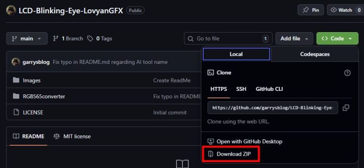
Feel free to try it it out and use it for your own projects or just use the images. You can copy the code and images from here, or download a zip file with everything from my GitHub here
Just click the <> Code menu and choose Download ZIP.
Finally
Now that it’s done, I can let it keep an eye on things. I can also say I’ve uploaded a blink sketch for the LCD, not just an LED.

Leave a comment