I’ve been working on building a weather station over the last few months and while I haven’t completed all the sensors, I have a few done including recently a rain gauge. The receiver is based around the “Random Nerd Tutorials ESP-NOW Web Server Sensor Dashboard” in which the data is displayed on a web page. Sensors use ESP32 microcontrollers and these send in their data using ESP-NOW. In a previous post I talked about some of my customisations to that.
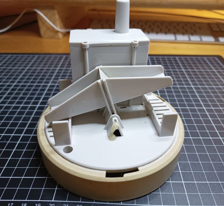
I started with the commercial rain gauge Aercus Instruments KW9015. This is a tipping bucket type that funnels rain into a small tipping bucket that tips back and forth like a seesaw. Each tip passes a magnet across a read switch. It worked well for many years, but it was missing one feature that I really wanted. It didn’t update the rain total in real time. It had current, 1 hour, 24 hours and total rainfall numbers, but the current didn’t seem to come through immediately. Other than that, I was happy with it.
This is a picture of the gauge with the top cover off. At the back of the tipping part is a magnet and there is a reed switch in the plastic box with all of the sender electronics.
Attempt at reverse engineering
Initially I tried to decode the data being sent with the goal of being able to make my own receiver with a 433MHz receiver and Arduino. This turned out to be just too challenging for me. I did learn that it sent a signal every 30 or so seconds and that the count that it sent was an increasing count, rather than just sending a “had another tip”. The advantage, I suppose, is that missed messages don’t matter, the count just picks up again when the next one gets through. I also did do some testing where I tipped the bucket with my fingers 100 times and waited for the received to display the amount of “rain”. From this I found that 100 tips is about 45mm of rain. This would be useful for calibrating my own receiver. Not long after this the sender module in it died.
Now that it was dead I didn’t feel guilty about stripping out the old electronics and converting it. Here is the original electronics. The board at the back is the 433MHz transmitter. The read switch is on the front board. All the smart stuff is done under the blob.

It really does not need a lot of complicated electronics. I used an ESP-32 module that I soldered onto a breakout board. I did this to reduce the current load. I added a Low Drop Out regulator with power coming from an old vape battery with a protection module attached. The ESP32 spends most of its time asleep. It wakes every 6 hours and makes a measurement of the battery voltage and sends that data to the receiver. I did this so I can monitor the voltage and ensure it is still operating. If the bucket tips the read switch pulls the pin it is connected to high and it wakes the ESP32 and sends in data.
Deep sleep or powered off?
I’m using deep sleep, but there is at least one other way I could have done this. While watching one of Andreas Spiess’ videos he talked about his mailbox monitor that is usually powered off. Opening the box triggers a MOSFET that turns on the ESP32. The ESP32 then turns a pin on that triggers another MOSFET that ensures holds the first one on until the ESP32 has finished doing its thing and then the whole thing shuts down. The beauty of this is that it doesn’t consume any power except when it has been triggered. Common ESP modules can be used as their power efficiency isn’t critical. The only downside is that no updates confirming it is running correctly are sent.
This is Andreas’ video. The whole video is an excellent resource on powering microcontrollers.
Ongoning count?
As mentioned, the original hardware would send a message every 30 seconds and it included the rain count. I decided to do something similar, so a count is sent every time the bucket tips and with the 6 hour timed updates. I thought this would be more reliable. The only problem I have had is that if either the sender or receiver is powered off it can mess up the days rain tally as values are reset. I’ve tried accommodating for that in my code, but I still don’t have it ideal. None of this would be an issue if I just sent a message that indicated “one more bucket count”.
The build
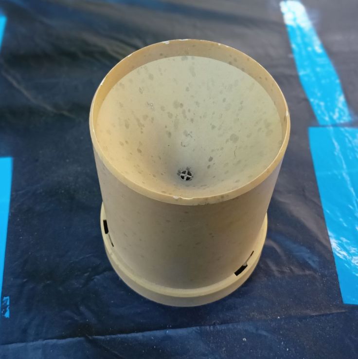
The existing rain gauge looked very tired. The plastic had yellowed, was stained and I was concerned it was becoming brittle. In an attempt to give it more life I cleaned it up and gave it a beautiful coat of paint with a more expensive spray paint. It looked better than new, Unfortunately I had not taken notice of the can and found that it started to flake off after a couple of months. The paint was for indoor use. Even so I think it may have been the cheaper outdoor primer that failed. There was nothing for it but to strip it back and paint it again.
With hindsight I could have fitted the battery and circuitry in the space the old electronics were. Instead, I used a large external box to house them. I’m still glad I did because I’ve found my projects tend to need a lot of ongoing tinkering and designing for that at the start makes that easier. The box is a waterproof one from Aliexpress. I’ve started to notice that two of the biggest cost of projects is often enclosures and paint.
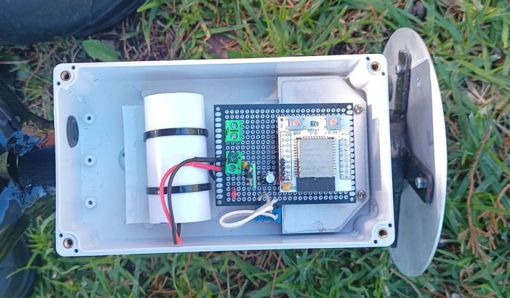
This is the new circuit board. Quite simple with room for later improvements or fixes.

Mounted inside the case. I am concerned that water may get in and wasn’t sure how to manage that. I decided to hang everything from a couple of mounting points at the top. After much thought I decided to hang the battery in a piece of plastic tube. The tube is mounted using cable ties to a piece of thin plastic that was used below the circuit board in an old PC power supply.
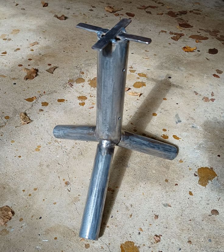
The stand started life as a speaker stand I made from old pipes. It was then modified to become a sprinkler stand. If I was making it from scratch, I would try and make the base wider, but hopefully it will not fall over. I welded a couple of bits of steel to the top and drilled a couple of holes in the side.
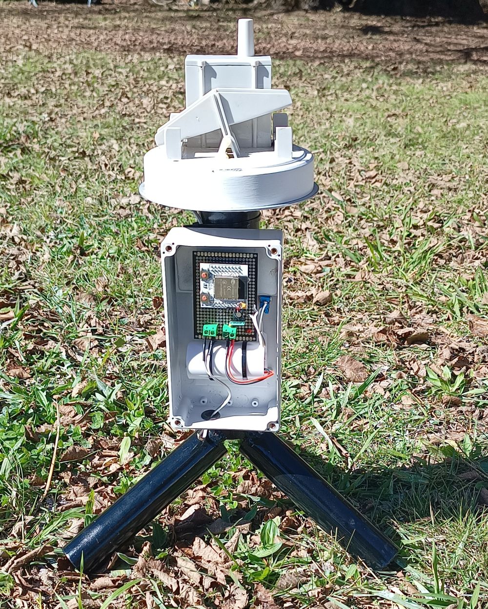
Here it is finished. It looks a bit top heavy, but most of the weight is at the bottom. The pipes are quite heavy. Time will tell if it is stable.
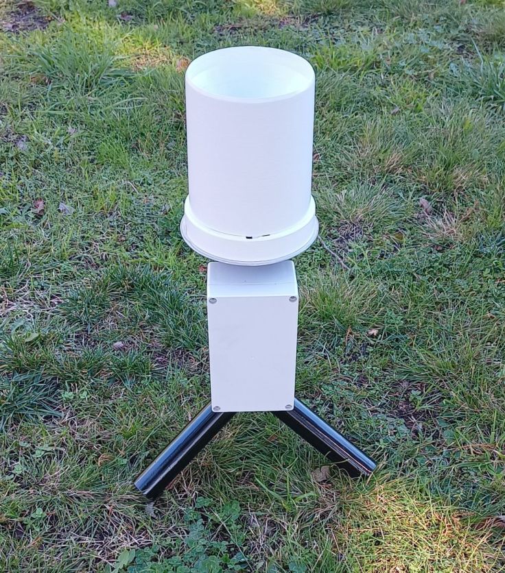
There is an on/off toggle switch mounted on the back of the box. It has a cover that is supposed to be waterproof. I’m curious how it will last.

Wrap up
I have not included the code because it is designed to work with a receiver I am still working on, but if anyone is interested, I can look at that.
It is fun watching the amount of rain increase during a storm, particularly when we need it to fill our tanks. Although, it would have been alarming if we had got the amount of rain some areas did a couple of weeks ago that are only 200 – 300km away here in NSW Australia. Some areas had over 700mm in 4 days, while we fortunately only had about 40mm.
I’ve already got a wind vane almost finished with an anemometer not too far away. I’ve also been testing a lightning sensor, that I’m excited about. After that I’m considering a seismic activity sensor.
I hope this has given you something to think about and perhaps some inspiration.

Hi Garry,
I recently read your excellent article on rebuilding the Aercus KW9015 rain gauge using an ESP32 with live updates.
Your approach to integrating deep sleep modes and real-time data transmission is impressive.
I’m Emily from PCBWay, a global PCB manufacturer in China. I’d love to sponsor your project with free PCB prototyping.
Would you be interested in collaborating? Feel free to contact me.
Best Regards,
Emily
Email: marketing@pcbway.com
LikeLike