

I’m not much of a gamer. I usually get bored with them easily, but in the madness of 2020 I purchased European Truck Simulator 2 and a Logitech G920 steering wheel and pedals. I enjoyed playing for a while but found there were not enough buttons on the controller for all functions. Some controls had to be accessed through the keyboard and I had trouble remembering what button to use for each function. I thought it would be fun to try and make a simple dashboard to go behind the steering wheel using button switches.
Rather than using a microcontroller I decided to use the module from an old USB keyboard as I already had a few old keyboards. The one I chose was probably an extremely cheap one. One benefit of that is that it doesn’t attempt to load manufacturer drivers or software. It just happily uses the generic windows drivers.
I pulled it apart to see what was inside. This one contained a small circuit board with all the smart bits inside a COB. The circuit board has a row of connectors that are held on to the two plastic membranes with a zebra strip.
Theseare the two membranes

And this is the small module. The smart bits are all under that COB. There are 3 LEDs on the ither side, for num lock and caps lock.

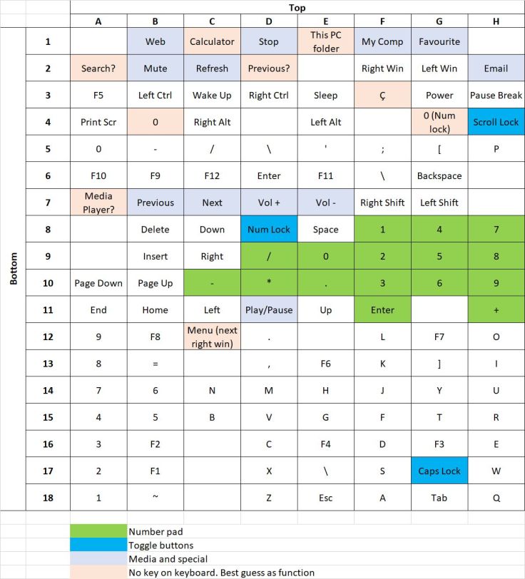
My idea was to place a bunch of momentary switches on a panel and wire them across the appropriate tracks on the keyboard circuit board. As I was planning on only using this for one game, I used the default keys for that game. Rather than figure out just the keys I planned to use I decided to try and work out what all combinations of track connections did. I discovered that there were some that were not available on the keyboard, for example the module supported a calculator button. In the end I made a table of the combinations. Even after testing it 3 times I’m not completely sure that I have it 100% correct. After starting I found this instructible Mapping the Innards of a Keyboard that I found very helpful. If you want to build something like this I recommend using that instructible. As I started before finding that article the table column and row numbers and letters I have used for the module connections are different.
The way I tested the combinations was to start by tracing the tracks from the two membranes back to the connectors. Then to check my results I opened Notepad++ and using a multimeter cable with a probe on both ends checked my results by shorting the connections on the module. The tracks are in two banks; one for the bottom membrane of button plastic and one for the top. It was just a matter of going through the combination of these two banks. I later found this site Javascript Key Event Test Script that shows info about keypresses which is helpful for those keys that are not for a number or a character.
Not all combinations gave an obvious result, but in the end it didn’t matter. I found there are other tables of combinations on the internet, but I presume there is not a standard that is followed so testing each one is probably required. This is the table I made from testing my module.
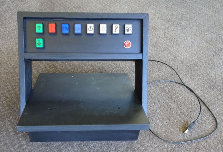
For buttons I used mostly illuminated momentary push button switches. I found some icons that I could use for symbols and printed these onto an overhead transparency sheet using a laser printer. These were cut out and put in the front of the switches. While it would be better to have the back light for a switch only illuminate when the function that it corresponded with is on, for example light when the truck handbrake is on, that is not possible with this setup, so the backlights were wired up across the USB power connections making them on all the time.

I notice that it is possible to buy these circuit boards from AliExpress USB Keyboard Chip IC Module HID Large Keyboard Can Be Used as Game Console, but they cost almost as much as a cheap keyboard, not that I recommend buying a keyboard for this. There are so many old keyboards around, most people wouldn’t have too much trouble getting an old one.
This is how it turned out. The steering wheel clamps onto the base.
Would I do it again? Probably not, even if I did play the game regularly, I would probably just get an old keyboard and stick labels over the keys and write the functions on them. While it functions as intended, I don’t think it was worth the work for my use and aesthetically I was fairly disappointed. However, maybe you can think of a use for a similar project that is worth it for yourself.

Hi Garrysblog 🙂
Thanks for your informations. Right now Im trying to create automated password filler with Arduino. My idea is that Arduino will connect such keyboard IC board in proper sequence. Is it important to know, which symbol is in which combination of Rows and Columns.
Thank You Again.
Paul.
LikeLike
Hi Paul. Interesting project. I’ve not tried that but rather than using a module like the one I used, you may be better off starting with a microcontroller that has built in support so that it can be programmed that to have the PC see it as a keyboard. A board with a ATMega32u4 is one type. I believe the Pi Pico can also be used for this. Also, the ESP32-S2 as well. This article has some info about using the ATMega32u4 https://maker.pro/arduino/projects/how-to-turn-an-arduino-into-a-keystroke-automation-tool
LikeLike
Hi there,
I’m planning to do something very similar to what you have done here, building up a panel (or three!) for Train Sim World.
Some functions require a combination of key strokes, eg. ctrl + p for instance. If I were to wire up both ctrl and p on the same switch to make the required connections at the time time on the same switch, do you know if this would have an effect on the function at all, or on other keys? Would I need a separate button for the ctrl part? My thinking is I’d be connecting 2 traces together so it would type / do something completely different.
Also, how did you provide power for illumination? I’ve seen some nice momentary 3 pin push buttons around, but am unsure about whether connecting USB 5V power to the same terminals as the ones for performing the key strokes would damage anything or not? Hope you can provide some assistance with this.
Thank you for your time,
George
LikeLike
Hi George. That sounds like an interesting project. The buttons all had LEDs built in and I connected those all to the 0v and 5v connections on the board for the USB input via current limiting resistors. The downside of my method is that they all stay illuminated all the time. Ideally it would have been nice it they were illuminated only while that game function was on, but that was beyond my skills.
I’m not too sure about using controls that need the two buttons pressed at the same time. I guess if your buttons had two poles then one could be used the ctrl button and the other for the other button. There may be other ways to do it with a keyboard module but I’m not sure how to do that.
Another method is to use a microcontroller which would be fairly cheap and shouldn’t be too difficult if you are familiar using Arduino, but there is the added learning curve if you have not used them before. Some Arduino microcontrollers can be used to be seen as keyboards by computers. This is one example by Ralph Bacon https://www.youtube.com/watch?v=rXz6eqhDPak.
LikeLike
Hi Garry,
Thanks so much for the response, much appreciated! I’ve managed to find some switches that have the Illumination contacts completely isolated from the switch contacts (I didn’t realise this was possible as I was only looking at 3-pin switches at the time).
I also think I can solve my problem of switching multiple keys using DPDT / DPST switches to switch each keystroke completely independently, but together with another for combinations of keys.
That’s beyond my skillset too but I think I’d be ok with them being permanently lit. 🙂
Thanks again,
George
LikeLike
The key word you need to know to prevent issues with keyboard chording (multiple keys, like CONTROL + C) is “ghosting”. When you build the matrix, you “just” need a diode across each vertex in the key matrix so that the thing generating the row/column scan codes can distinguish a connection from all the connections “inside” the matrix from the pressed key. Hackaday had an article on this recently, IIRC.Lots of small microcontrollers like BL602/BL702/BL616, many of the newer RISC-V ESP32s, and several of the WCH parts like CH453, CH455, or CH9329 (look up numbers before ordering—my memory isn’t so good these days) have matrix decoders on board that can save a LOT of fussy wiring and programming.
LikeLike
I’ve seen internet entries saying that soldering on the pcb contacts is pain in the A. How you did it? I want to follow your instructions you did a great job soldering
LikeLike
I don’t remember it being particularly difficult. I did give them a good clean, probably with a pot scourer. They are reasonably close together that’s a little challenging. I tend to shake a bit when I’m soldering. To help with that I make sure the board I’m soldering is held firmly and low. I usually use blu Tack to hold it onto a board or cutting mat. If you do that don’t place the Blu Tack too close to the part of the board that will get a lot of heat or it goes very sticky. With it held down I can then rest the palm of my hand on the desk while soldering.
LikeLike