Whenever someone pointed out to a work colleague that there was an easier way to do what he was attempting, he’d look confused and then reply, “Well, anyone can do it the easy way.” I seem to find myself avoiding the usual easier way with projects, just to try do it differently. That’s how I came to try and use a magnetic compass module in a wind vane.
An important part of the home weather station that I am building is a wind vane, and I had a cunning plan for how to make it work. I have a spare HMC5883L three axis compass module. The idea was to keep the module stationary, place a small magnet above it on the vane shaft, and have it report the vane angle. I figured a small magnet would overpower Earth’s magnetic field, but not enough to swamp the sensor. I was well pleased with myself. I did some googling and found where someone mentioned that if using a magnet with one, make it small or it will swamp the sensor.
I even put my idea to ChatGPT and it came back enthusiastically with, “Awesome project! A magnet-on-vane approach with the QMC5883L is a clever and elegant way to make a digital wind vane.” I got ChatGPT to help write some demo code and that worked, well sort of. I don’t think there was an issue with the code but looking at the output for each axis it looked like the sensor was getting swamped by even the smallest weak magnets that I have. That seems to be a problem with ChatGPT, it tends to be very encouraging, even if your idea isn’t all that great.
I then thought I should investigate something actually designed to do this. I had not done that because I thought dedicated ICs for this are extremely expensive. Perhaps they once were, but they are not now. I decided to go that route. If you are looking for these, the key search words are; magnetic, encoder and angle.
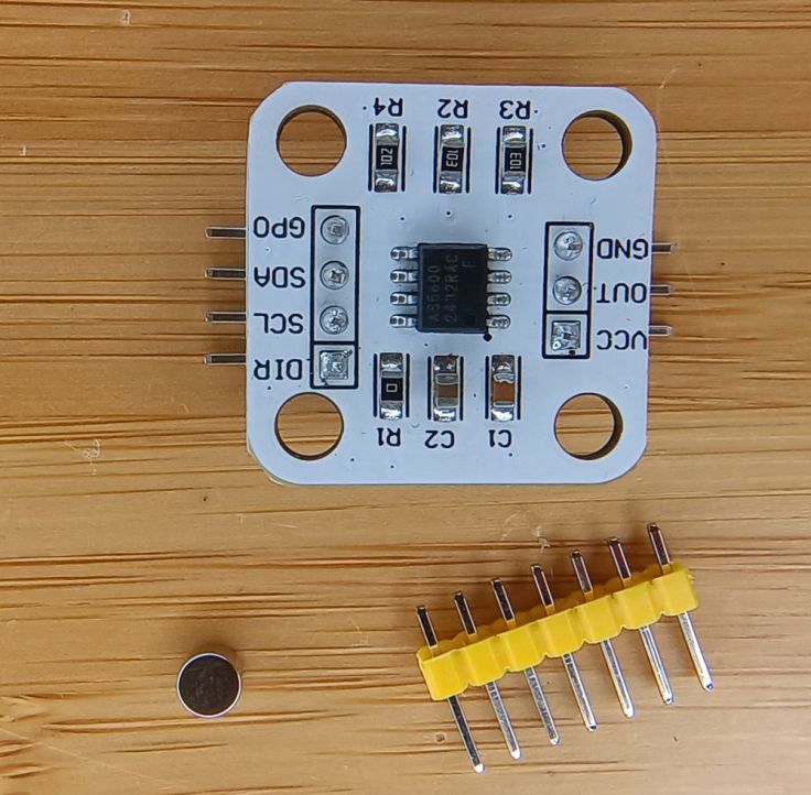
I purchased two different modules. The first was AS5600 encoder modules. I got a pair for AU$3.97.
I also got a single MT6826S module for AU$5.55.

These modules are designed to give the angle of a shaft. A circular magnet is placed on the end (not side) of the shaft and the modules IC/sensor is placed below the magnet. They look like standard flat disc magnets, but they’re not. Instead of having north on one face and south on the other, they’re polarised around the edges; north on one round side, south on the other.
I started with one of the AS5600 modules. It interfaces with I²C which made it fairly easy to use, well, with an issue I’ll cover later.
Building the hardware
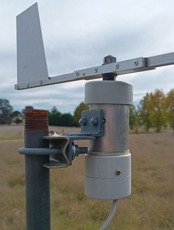
I have made a few spinning things that I have mounted on a pole. They have no purpose, they just spin in the wind and are interesting to look at. What I have discovered is that bicycle hubs are fairly easy to obtain, work well, easily maintained and last for many years. I have a bicycle wheel that has been spinning for about 20 years. The anemometer looking thing is just a bunch of soup ladles mounted on a bicycle hub. It will remain, but will not be used for the anemometer as it is fairly rusty now. The new wind vane is on the right.
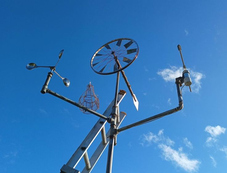
Using a hub seemed like a good foundation to start and I like to use up things I have. My idea was to bolt a vane on one side of the axle. Place a magnet on the other end of the axle and place the sensor below that.
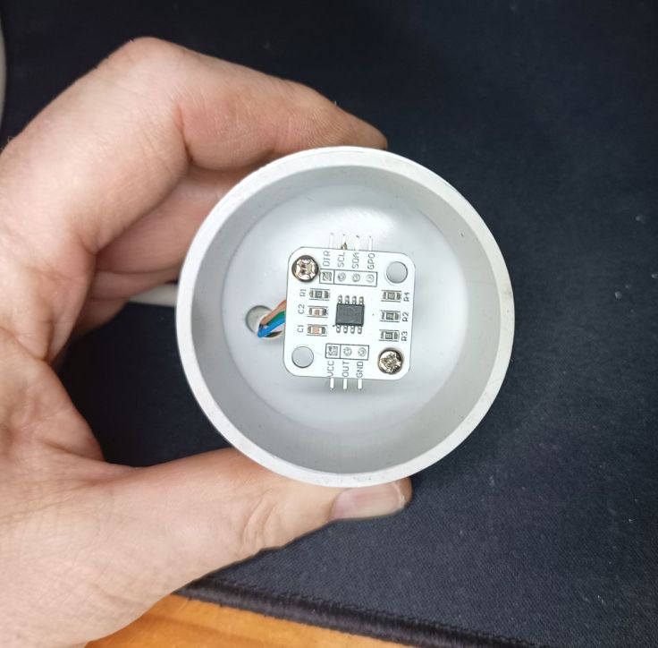
There is a U shaped piece of steel between the bracket and the hub. This is to stop the hub pivoting. The PVC parts on the right form the housing for the sensor and is made up of a piece of 50mm PVC pipe and two end caps. I enlarged three of the spoke holes in the hub for bolts to go through. There is a rubber washer there as well. That came off a water filter. I added it in the hope that it would reduce water getting into the electronics.

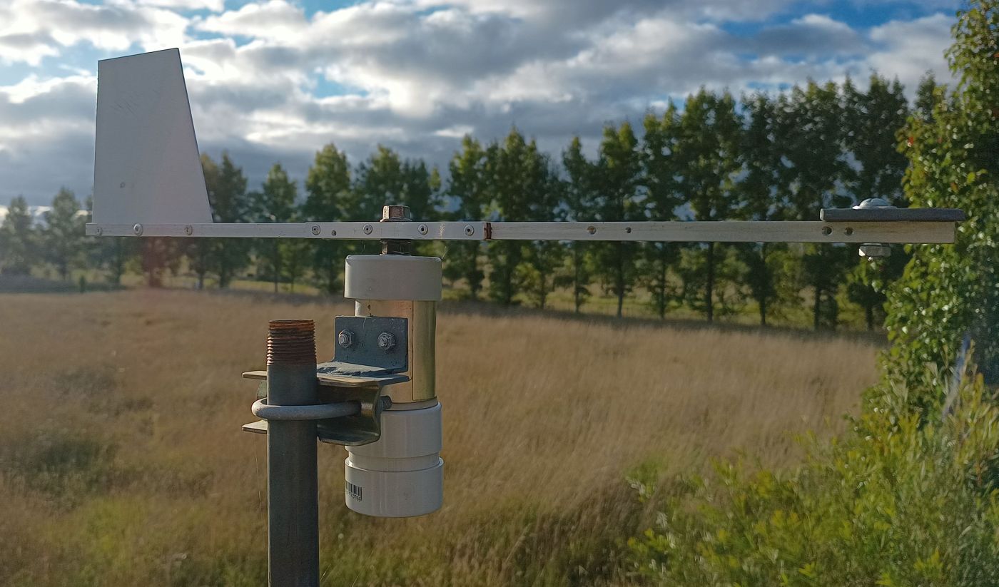
In the first images you may notice that the support bracket looks different to what is in the later ones. That’s because I rebuilt the mounts after realising it was going to result in the anemometer and vane being too close together, possibly affecting the wind speed readings.
Here’s an end-on view, showing the magnet glued to the axle
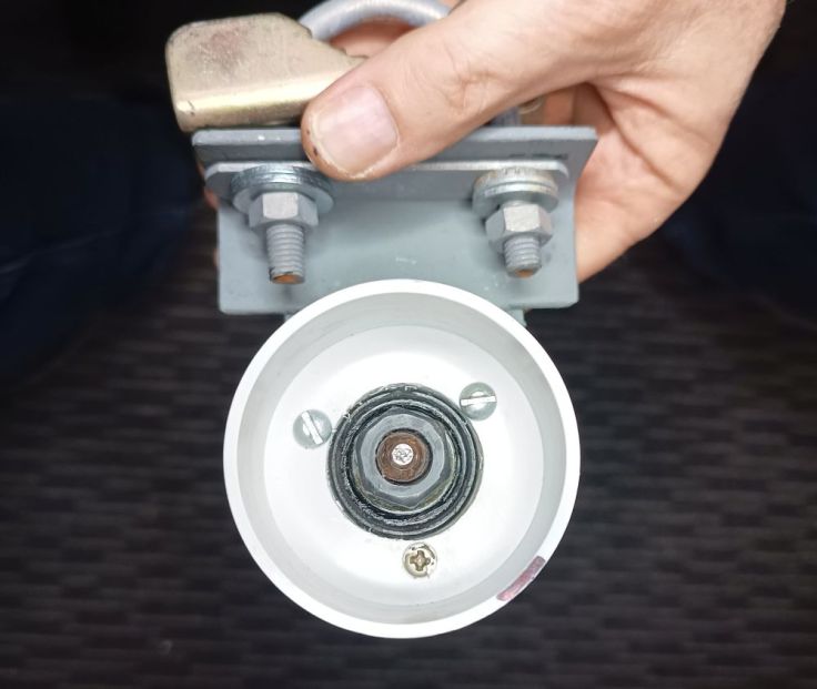
The sensor board was mounted to the bottom endcap using two standoffs. These placed it a few millimetres below the magnet.
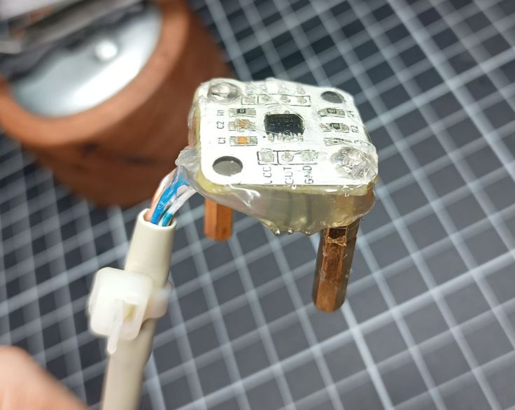
I coated the sensor with hot melt glue to provide a sort of conformal coating to protect it from moisture.
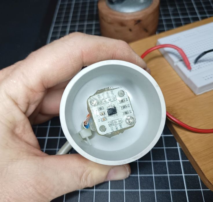
Here it is fastened in again. There is a bit of space below the module. Any water that does makes its way in should exit the bottom without getting on the sensor.
The vane was made from four pieces of aluminium that I had pulled out of some old equipment. I cut a slot down one length, cut a piece of flat aluminium for the tail and riveted it all together. Unfortunately I don’t have a good picture of this, but this one may help.

And this one.
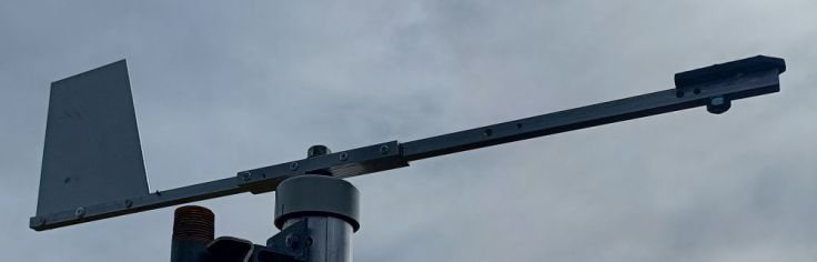
Initially I didn’t have a weight on the nose. However, without it the vane wasn’t balanced. That may be ok if the axle was perfectly vertical, but I wasn’t going to be able to manage that. If it was just a little off, and the wind was low, the heavy end of the vane (the tail) would swing around so it would be at the lowest point.
Fancy cover
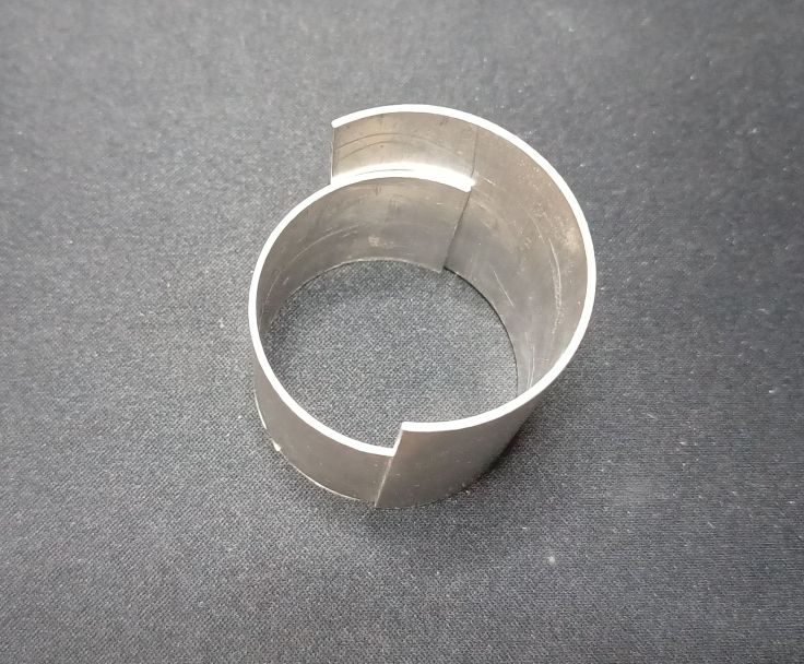
The hub is steel and I presume it will start to rust with time. I had a piece of aluminum pipe and decided to make a housing to go around the hub, for protection and aesthetics. I cut two lengths of pipe and then cut pieces out of each lengthwise. One was smaller, had holes drilled for the U bolt and then fastened between the hub and pole mount with the U bolt. I don’t have photos of this, but I do have photos of these short offcuts.
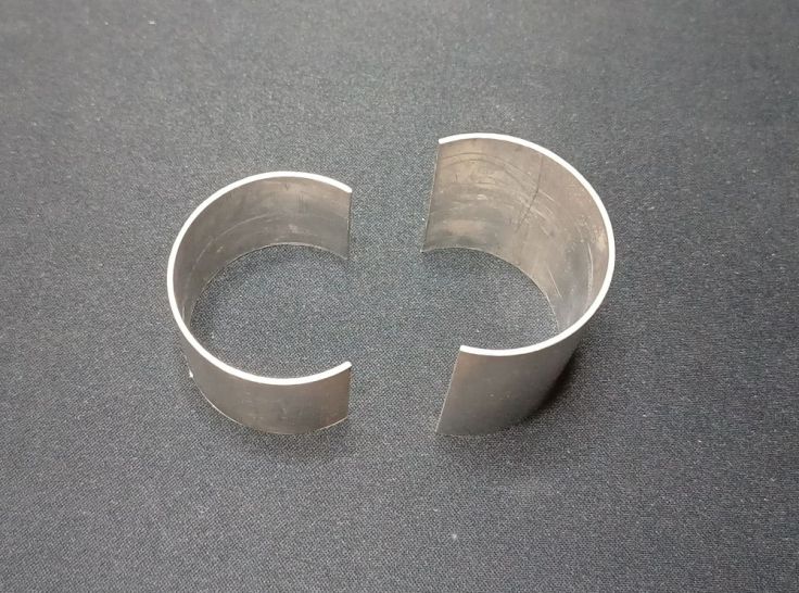
The bigger piece just clips over the small piece. Friction holds them together.
More water protection
Another PVC end cap had a hole drilled and was bolted to the top of the axle between the top hub cone and another nut. Above that the vane was fastened with another nut.
Cabling with I²C
I found some old AV cable. It had two shielded pairs, similar to a stereo audio cable. I thought this would be ideal and connected it all together. This is when I learned my next lesson. I²C is Inter-Integrated Circuit (not Inter-International Cabling), that is designed for connecting ICs together, not for a scaling a pole. When I attempted this the EP32 didn’t even see the sensor. After some googling and chatting with ChatGPT I found that the distance can be extended, however I did see many comments that said using I²C for significant distance is a bad idea.
I found where a commenter said they used Cat5 cable. I followed their method:
- One pair twisted together for VCC
- One wire from the second pair for SDA
- One wire from the third pair for SCL
- Both wires from the fourth pair, plus the two unused wires, all connected to GND.
Both ends were connected the same. You can see the cable at the top of the board.

The other part of this is modifying the software. I slowed down the I²C clock speed to 50kHz to improve reliability. I did this by changing the Wire.begin() line:
Wire.begin(SDA_PIN, SCL_PIN);
To this:
Wire.begin(SDA_PIN, SCL_PIN, 50000);
This is more info about I²C on the Espressif site.
I don’t know if this is good, best or recommended, but it worked. It is only covering a distance of 4.5m.
Controller enclosure
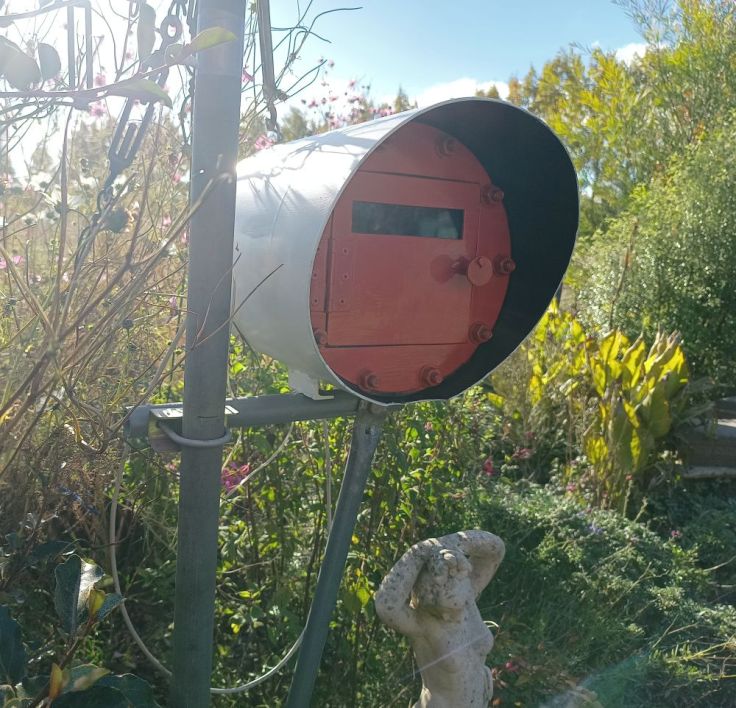
I had an old mailbox I made from a pump pressure tank. It was a decent mailbox, but too small for those AliExpress packages. It had been laying on the ground for a couple of years. I decided to clean it up.
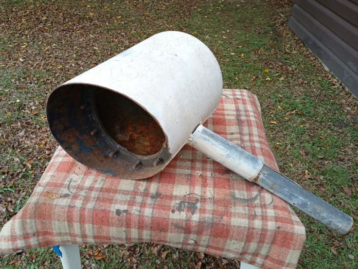
After a lot of preparation, painting and mounting, I am very pleased with it. Do you like the inspection window made from a scrap of Perspex?
I need to build a better housing for the actual electronics. I still need to do some tweaking and finish the anemometer before doing that. At the moment it is just sitting in a takeaway container. Surprisingly I’m not having issues with it sending data to the receiver even though it is sitting in a metal housing.
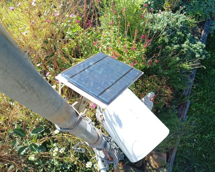
A small 6V solar panel has been mounted onto a TV masthead amplifier bracket I’ve been holding on to for about 40 years. See one day that junk does come in handy 🙂
Software
Averaging
I discovered that the vane would sway a bit. It seemed that it would turn into the wind, overshoot a bit, swing back, overshoot a lesser amount, and so forth. I’m guessing this is to do with the design and weight of the vane. It doesn’t seem to be too bad and so I thought I would allow for that in the software. My plan was to take 10 readings, 6 seconds apart and then average them and use the final value. This way the web page would have an updated value each minute.
Where this fell apart is that I simply added up 10 angle values and then divided the total by 10. The problem I later discovered is this is not the way to do it. It became obvious when I started seeing south displayed when the wind most coming from a northerly direction. I suspected it was my averaging. Some Googling confirmed it. If two readings are made 350 and 10 an expected values is 0 (north), but my method of averaging gave 180 which is south. I learned the way to do it correctly is to convert the angles to vectors (sine/cosine), average those, then convert back to an angle. I’ve forgotten all the trigonometry that I learned at school, so got ChatGPT’s assistance with this.
Cardinals
I don’t mean those high ranking officials in the Catholic church. In this context I’m talking about in North (N), East (E), South (S) and West (W). Apparently Northeast (NE), Southeast (SE), Southwest (SW) and Northwest (NW) are ordinals. I wanted these to display as well the angle from North. I did experiment showing the secondary intercardinal directions as well, these are NNE, ENE, ESE, etc. I found it too difficult to visualise these in my head so went back to just the 8 cardinal and ordinals. Wikipedia has an interesting page about Cardinal direction if you are interested.
Example code
Here is some example code that mainly come from ChatGPT. I’m not using this exact code, but something based on it. My code includes sleeps and transmission via ESP-NOW using code based on my previous post Customizing the Random Nerd Tutorials ESP-NOW Web Server Sensor Dashboard.
This code does not use any library for the sensor. Connections are listed in the code. It’s fairly simple, only the sensor module and ESP32 are needed.
/*
  Example code for AS5600 Magnetic Angle Encoder

  Connections
    AS5600  	ESP32
    ------    -----
    VCC	      3.3V
    GND	      GND
    SDA	      GPIO 21
    SCL	      GPIO 22

*/

#include <Wire.h>

#define AS5600_ADDR 0x36      // AS5600 I2C address
#define SDA_PIN 21            // Your ESP32 I2C SDA pin
#define SCL_PIN 22            // Your ESP32 I2C SCL pin

float calibrationOffset = 0;  // adjust this value to align with North

void setup() {
  Serial.begin(115200);
  Wire.begin(SDA_PIN, SCL_PIN, 50000);  // Slows I2C to 50kHz for long wires
  Serial.println("AS5600 Angle Sensor Ready");
}

void loop() {
  uint16_t rawAngle = readAS5600Angle();
  float degrees = (rawAngle / 4096.0) * 360.0;
  String compass = getCompassPoint(degrees);

  Serial.print("Raw: ");
  Serial.print(rawAngle);
  Serial.print(" | Degrees: ");
  Serial.print(degrees, 1);
  Serial.print(" | Compass: ");
  Serial.println(compass);

  delay(200);
}

// Reads data from the sensor
uint16_t readAS5600Angle() {
  Wire.beginTransmission(AS5600_ADDR);
  Wire.write(0x0E);  // ANGLE (MSB)
  Wire.endTransmission(false);

  Wire.requestFrom(AS5600_ADDR, 2);
  if (Wire.available() == 2) {
    uint8_t msb = Wire.read();
    uint8_t lsb = Wire.read();
    return ((msb << 8) | lsb) & 0x0FFF;  // 12-bit mask
  }
  return 0;
}

// Converts angle in degrees to compass point
String getCompassPoint(float angle) {
  const char* directions[] = {"N", "NE", "E", "SE", "S", "SW", "W", "NW"};
  int index = int((angle + 22.5) / 45.0) % 8;

  // Flip for compass convention (clockwise)
  //angle = fmod((360.0 - angle), 360.0); // Uncomment this if East and West are flipped

  return String(directions[index]);
}
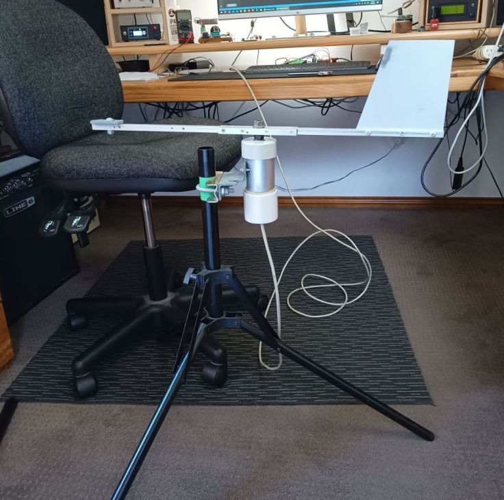
Testing
For testing I mounted it on a stand that I had and checked to ensure that N, S, E and W were all where I expected, 90 degrees apart. During one test North and South were correct but East and West were off. I’m wondering if the magnet was not centered above the sensor. I moved the magnet and the reading was correct.
Finally
This has been an interesting project. It was harder than I expected, but I’m happy with the results. As well as functionality, I like the look of the aluminium and white PVC combination of the vane.
Since the first sensor worked well, I never tried the other type. Now I’ve got two modules sitting in my parts bin ready for another project. I wonder if I could use as part of a rotary tuning knob for a digital radio? Here I am again thinking of using something for something it isn’t designed for. I wonder if ChatGPT would approve?
I hope it has given you some inspiration or entertainment. As usual, let me know if you see any issues or improvements. Next up I expect to do a post about a sorry tale of an anemometer I purchased.

Leave a comment