I have had one of those cheap ISD1820 audio recorder and player modules sitting around for a long time. I thought it may make a fun message recorder to leave on the kitchen counter and see how it gets used. I was thinking it may be used as an alternative to leaving written messages, but I think it will be more likely it will just be used to record raspberries and fart sounds.
Mysterious audio
Recorded audio is retained in memory even when the module is not powered. When I connected power and pressed play on my module mysterious audio played and it was a few moments before I remembered what it was.
Years ago, I had recorded the audio and set it to play in a loop. The message was just a stream of numbers with sound effects. While I was speaking and recording the stream of numbers I added the sound effects by twiddling the dial of a SW radio to add in some of those great weird sounds that are common on SW. It was then set up with a small FM wireless microphone with its microphone near the module’s speaker. I secretly turned it on when a friend came to visit and told him how I had discovered a spy number station on the radio. I tuned in a radio that had both SW and FM to the frequency of the FM transmitter. I was hoping that he would not notice that we were on FM and not SW. It wasn’t too long before he laughed and realised what was going on. He laughed because those numbers had a particular significance in our childhood.
This is the mysterious audio from the module.
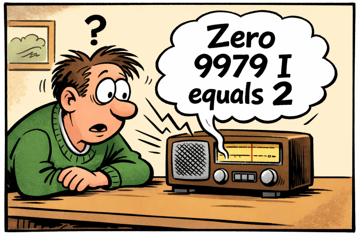
The incident, as envisaged by ChatGPT.
Features
The features that I was aiming for were:
- A decent speaker. I used a speaker from a secondhand surround sound system. These are great audio for projects.
- A power switch to reduce battery drain.
- A power LED. This is so alert others that there is a message and also to reduce battery drain by ensuring that it is not left turned on.
- An external microphone from an old headset.
- 2 buttons from the module to go to broken out to the outside of the case; play (PLAYE) and record (REC).
- No holes or permanent fixtures to the speaker case so that it could be repurposed.
- Adjustable frequency control to vary sampling frequency/speed/recording length. This was added in later after reading Modifying An ISD1820 Voice Recorder Board breaking out the controls and making a lo-fi sampler
Power
In at least some of the eBay listings for the module, it lists the supply voltage as 3-5V. I decided to use 3 x AAA batteries as this would ensure it would be in that range even when the batteries start to go flat. However, I have since noticed that other articles and the chip datasheet lists the supply voltage as 3V, so I may be supplying too much voltage. Also thinking about it after completing it, I could have used a Li ion battery from one of the vapes that I found along with a charger module.
Build
If possible, I wanted to only use parts that I already had, and I was able to do that. The case was a cheap plastic one that I had used before. It would have been simpler and just as good if I used the microphone that came with the module, but I decided to use a microphone from a broken Microsoft headset. I already had some new switches and LED.
While looking at options for a battery holder I found I had a few converters that I had removed from some old LED torches. These hold 3 AAA batteries and importantly it would fit in the enclosure I had.
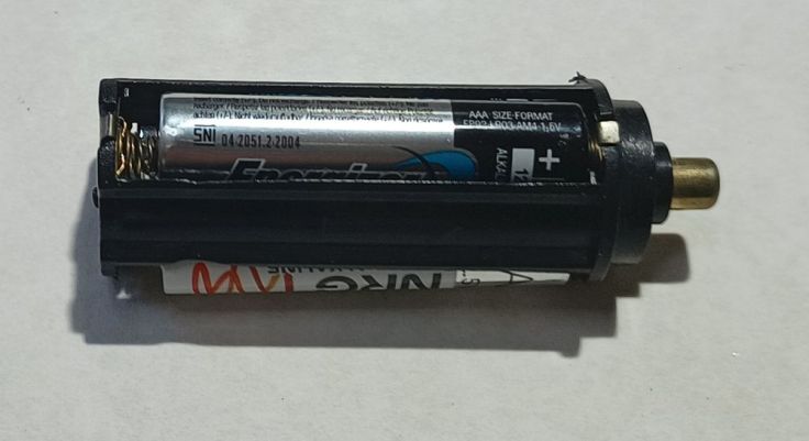
They have two terminals. The negative is a flat tab on the bottom and the positive is at the top and is connected internally via a spring. I initially thought I would install it vertically, so I removed the top of the holder, including the spring. I didn’t end up using it that way, but that didn’t matter. The real trick with using it was soldering the connections. I use lead free solder that has a high melting point and the plastic melts easily. I doubt that the fumes are healthy. I used some flux paste and soldered quickly. It only takes a few seconds for the plastic to start to melt, so I don’t recommend using these, but in this case it worked.
The board has 3 buttons and these are broken out to the header pins on the board.
- REC – Hold down while recording audio
- PLAYE – Plays the entire recording with a short press
- PLAYL – Only plays while button is held down
I didn’t need to touch the buttons on the board as there are header pins for those. For PLAYE I connected a switch between the PLAYE pin and Vcc and for record another switch between the REC pin and Vcc. While I don’t want to buy many more parts, a few easily to mount push buttons is starting to look like a good investment. The ones I used required a lot of bodging and hotmelt glue to mount them. I wanted coloured buttons but I only had black tops. Simple I incorrectly thought. I’ll just paint them. I have some old enamel paint for models. I painted one red and that went well. I then I tried white only to find that it had gone blobby and no amount of mixing got it good enough. That didn’t stop me ruining two button tops. In the end I gave up and just used a black one.
For a power LED I connected an LED in series with a 1K resistor with battery negative and the board side of the power switch so that turning on the switch turns both the module and LED on.
I glued the lid of the case to the back of the speaker case with hot melt glue. This is holding well and will allow it to removed from the speaker if I want using Isopropyl Alcohol. I expected that I would simply clip the module box onto its lid and the clips would hold it. Ahhh, no, they are not very strong, so I used a bolt to go right through the module case and into a thread that is built into the speaker.
Variable recording length/speed/recording
After I completed the build I found Modifying An ISD1820 Voice Recorder Board breaking out the controls and making a lo-fi sampler. It shows an easy mod by changing a resistor the inbuilt oscillator speed can be changed allowing the maximum recording length to be set between 8 – 20 seconds. The interesting bit is that by using a variable resistor, the speed and resulting pitch of the recording can be changed during playback. This sounded like an easy bit of fun so I added that in.
On my board the resister that sets the oscillator frequency is labeled R2, while on some others it is R4. The resistor is in the same physical location, but for some reason the labeling is different. The datasheet lists a recording time of 8 seconds to 20 seconds by using resistors from 80K to 200K. I only had a 100K pot, so I decided to use it with a 100K fixed resistor in series.
This gives a recording length of between 10 – 20 seconds. That doesn’t give the full range but is enough for some fun.
Circuit diagram
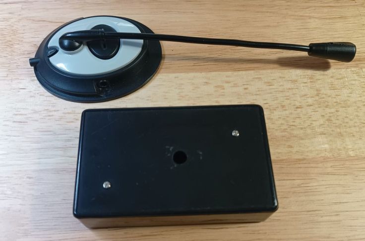
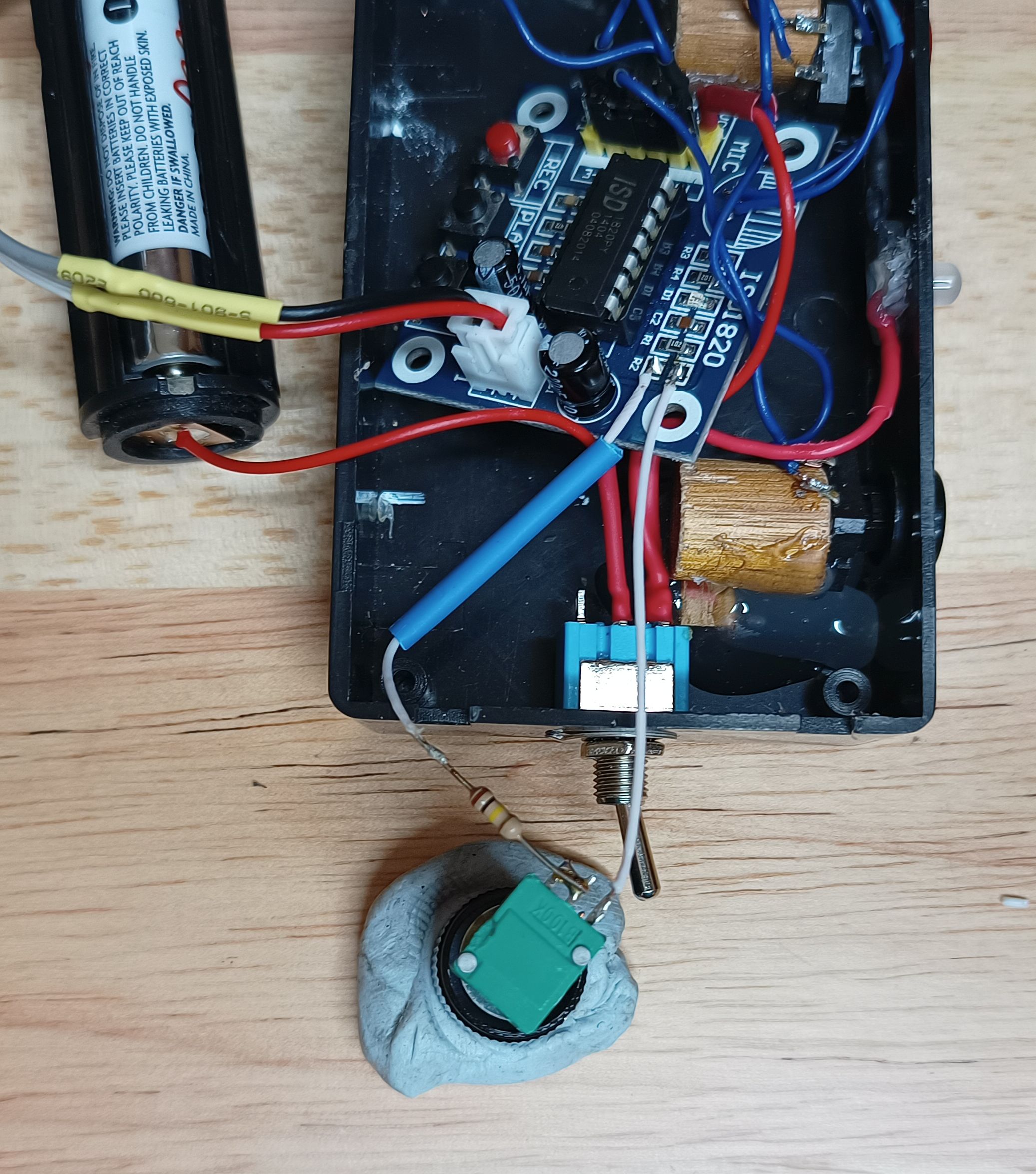
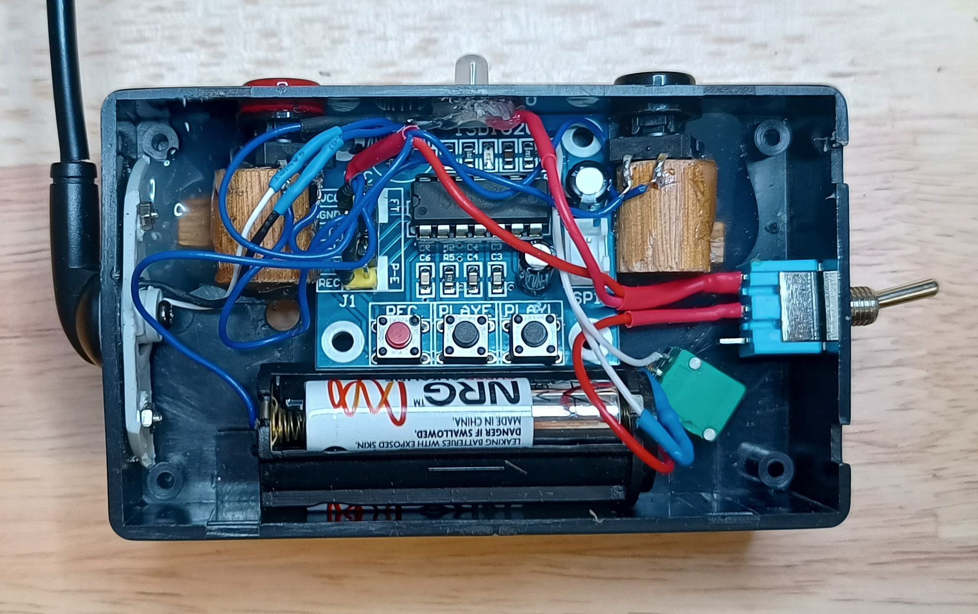
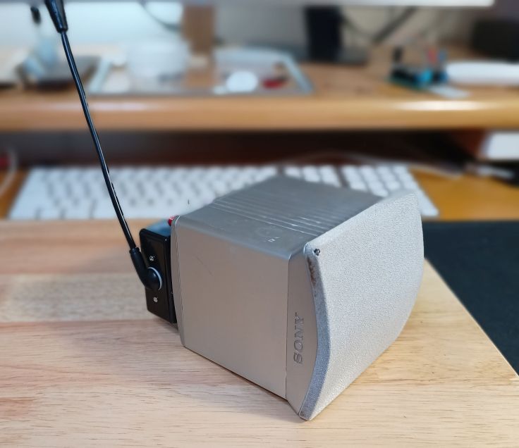
A view of the internals.
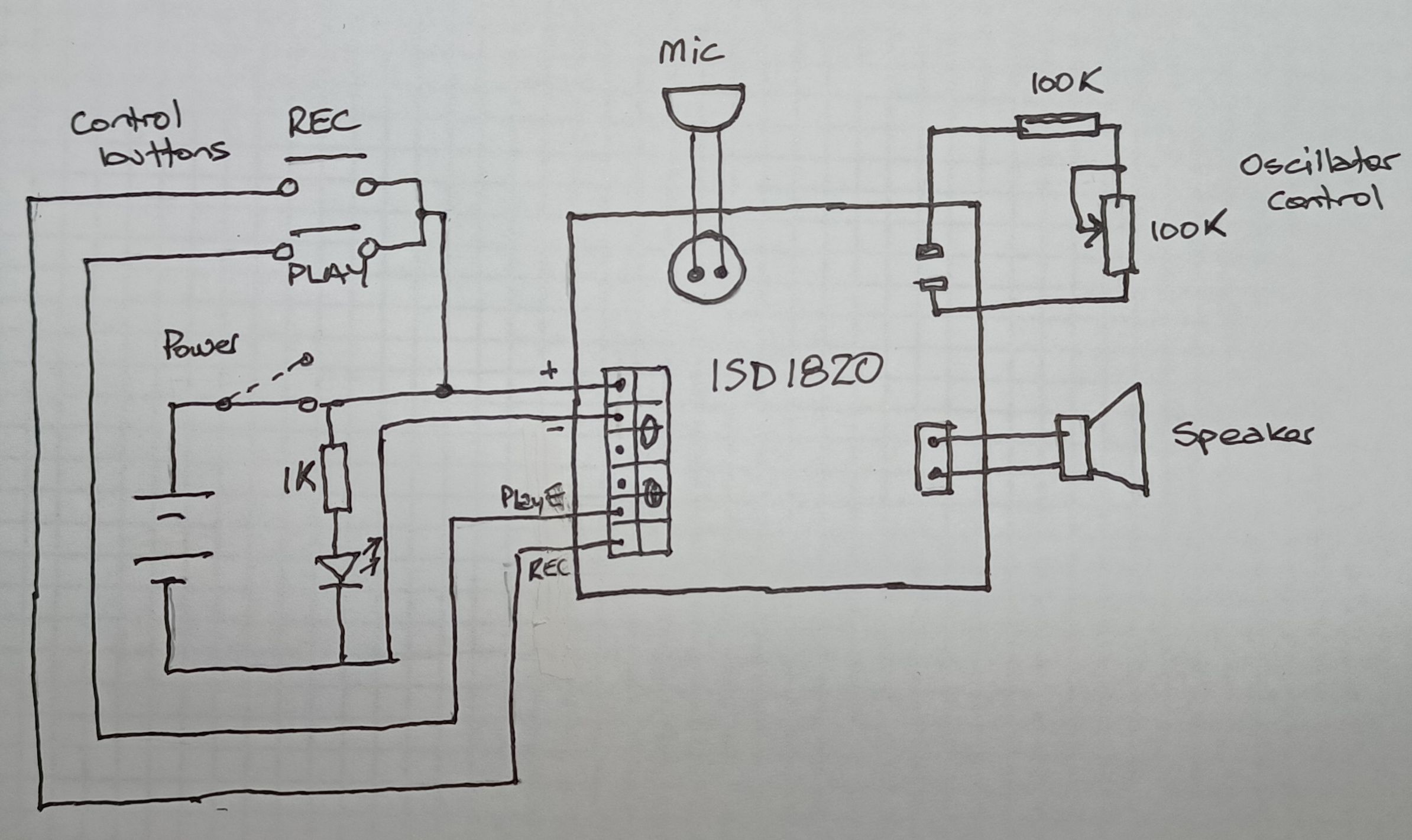
This is the circuit diagram.
Result
So how has been. Well, it hasn’t been used much yet, but so far only for recording silly sounds. Only time will tell if it will have been worth it. I’m not an expert, just a hobbyist, so I may have made mistakes or missed something. Let me know if you can see any mistakes, or improvements or other possible uses.
Useful links
ISD1820 Voice Recorder Module User Guide. A user guide for the module at Phipps Electronics. It includes a schematic of the board.
Modifying An ISD1820 Voice Recorder Board breaking out the controls and making a lo-fi sampler. Information about how to change the recording length/sampling frequency.
How To Use ISD1820 Voice Recorder and Player. An Instructable about the module.
Banner image
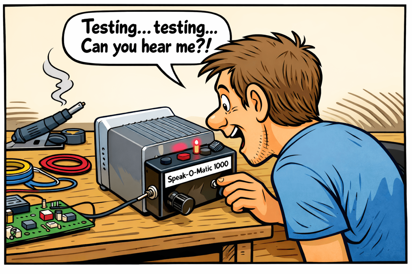
The banner image was generated by the AI image generator that is available in wordpress.com. I’ve decided to try and learn how to use it to generate images in different styles. I like the graphics that are used in old magazines and books like Popular Mechanics. The prompt I used for this image was “Generate an image of a man talking into a small box that has 3 buttons on the front and a small microphone sticking out of the top. It is sitting on a table. Make it in the style of a drawing from a 1970’s book for boys”

Leave a comment